

First flush water diverter
a technology of first flush and water diverter, which is applied in the direction of drinking water installation, water supply tanks, gas/liquid distribution and storage, etc., can solve the problems of insufficient length of pipe, no rainwater first flush diversion system, etc., and achieve the effect of reducing the volume of rainwater carrying capacity
- Summary
- Abstract
- Description
- Claims
- Application Information
AI Technical Summary
Benefits of technology
Problems solved by technology
Method used
Image

Examples
Embodiment Construction
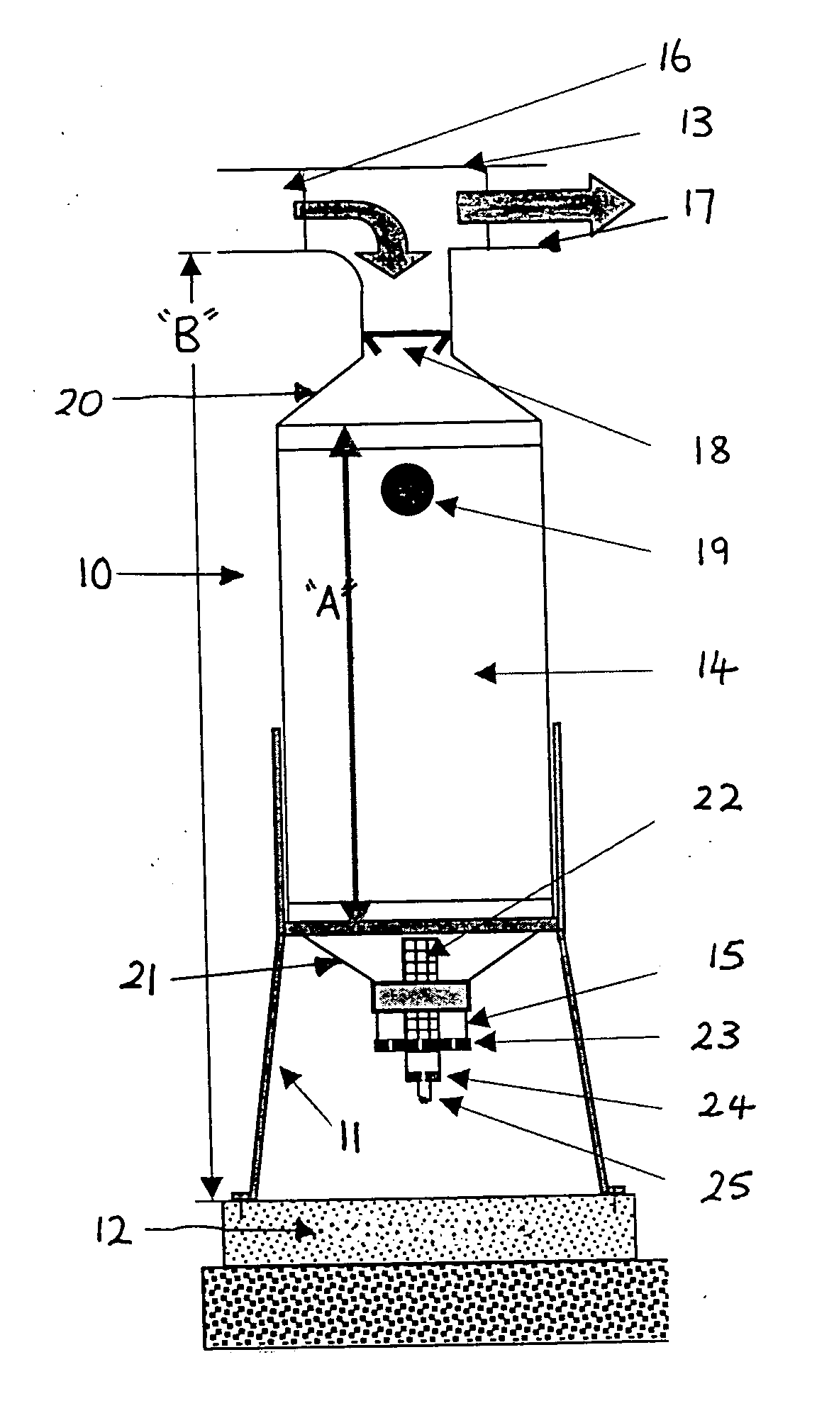
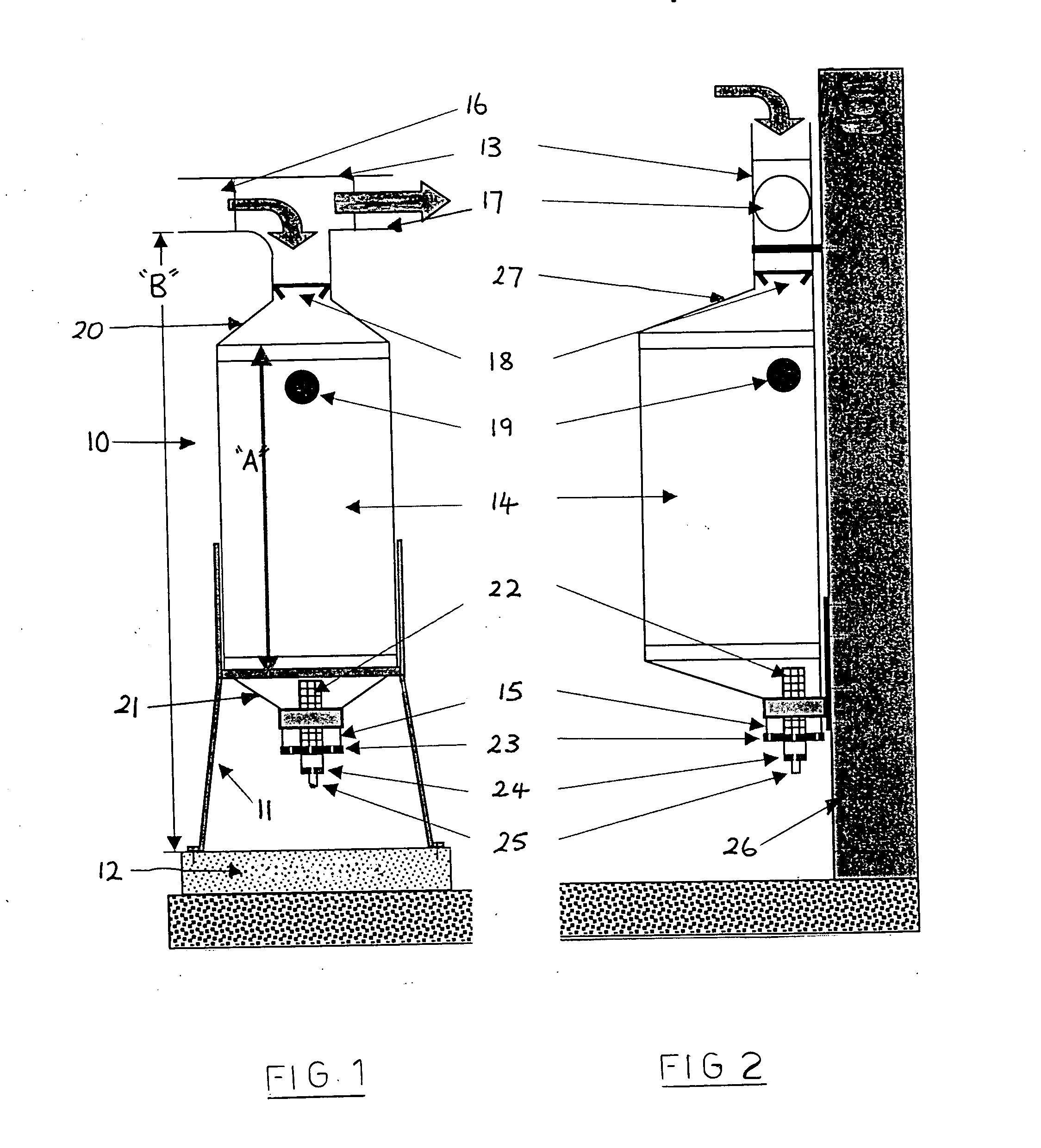
[0017] Once the required rainwater carrying capacity for the collection chamber has been determined for a particular roof area, using the aforementioned formula, it is then simply a matter of ascertaining what length of standard diameter collection chamber meets this requirement. For a typical collection chamber, formed from cylindrical pipe having a diameter of 300 mm, suitable lengths for specific volumes are provided in the following table. This table also indicates the total height required between the ground and the level at which the rainwater flows along the T-piece into the collection chamber. This height takes account of the space required for the outlet and associated flow control valve which are typically located below the chamber.
Capacity ofLength ofHeight between T-Collection ChamberCollection Chamberpiece inlet and(liters)(mm)ground (mm)202255903036573040500865506309956078011457090512708010501415901180154510013101675120161019751301735210015020052370
[0018] The collect...
PUM
 Abstract
Description
Claims
Application Information