
System and method for regulating the volume of barrier fluid in a liquid ring vacuum pump

a technology of liquid ring vacuum pump and barrier fluid, which is applied in the direction of liquid bottling, liquid dispensing, packaging under special atmospheric conditions, etc., can solve the problems of increasing the volume of the impeller cell, creating a vacuum, and bending of the impeller blade, etc., to achieve accurate regulation of the volume of the barrier fluid, simple and cheap, and easy maintenance

Active Publication Date: 2005-04-21
AES ENG
View PDF6 Cites 11 Cited by
  • Summary
  • Abstract
  • Description
  • Claims
  • Application Information

AI Technical Summary

Benefits of technology

[0039] Embodiments of the present invention seek to counteract the problems suffered by prior art systems and methods. Embodiments of the invention seek to accurately regulate the volume of barrier fluid in a liquid ring vacuum pump. Embodiments of the invention overcome the risks associated in manually controlling the barrier fluid by automatically regulating the volume of barrier fluid in a liquid ring vacuum pump. Embodiments of the invention seek to regulate the volume of barrier fluid using a system that is generally simple and cheap and easy to maintain. Embodiments of the invention seek to regulate the volume of barrier fluid in a liquid ring vacuum pump using methods that are relatively simple and cheap.

Problems solved by technology

This leads to an increase in the impeller cell volume (the space formed between the liquid ring and root of the blade) that in turn leads to the creation of a vacuum.
This may cause the blades of the impeller to bend and possibly break.
Pump failure may also occur if the pump has too little fluid.
The pump will be unable to create a vacuum, the pump may run dry or cavitation may occur which may subsequently cause damage to the internal structure of the pump.
Unfortunately, the volume of barrier fluid within the pump may vary.
For example, barrier fluid may leak from the pump.
Barrier fluid may evaporate if it becomes too hot.
Also, sudden changes in temperature and / or pressure may result in either a loss or increase in barrier fluid.
Thus, the barrier fluid is replenished using trial and error and this often leads to an over-supply or under-supply of barrier fluid in the vacuum pump (1).
A manually controlled valve is also prone to human error.
Therefore, the pump (1) has a high risk of failing.
However, this solution is costly and difficult to implement, it unduly increases the complexity of the system and produces a system that is both costly and difficult to maintain.

Method used


Image

  • System and method for regulating the volume of barrier fluid in a liquid ring vacuum pump
  • System and method for regulating the volume of barrier fluid in a liquid ring vacuum pump
  • System and method for regulating the volume of barrier fluid in a liquid ring vacuum pump

Examples


Embodiment Construction

[0047] The system for regulating the volume of barrier fluid depicted in FIGS. 4, 5 and 6 comprises a vessel (16) which retains a quantity of barrier fluid (16′). The vessel (16) is connected to a liquid ring vacuum pump (19) by a feed pipe (17) and a return pipe (18) using the appropriate pipe connectors (not shown). A “loop” or “circuit” is formed such that barrier fluid is discharged from the pump (19) into the vessel (16) and drawn from the vessel (16) into the pump (19). The size of vessel (16) is selected in accordance with the size of pump (19), which in turn depends on the particular application in which the pump (19) is to be used, as will be understood by the person skilled in the art.

[0048] As noted above, any given liquid ring vacuum pump contain have an optimum amount of barrier fluid for optimum operation of the pump. The optimum amount of barrier fluid is conveniently determined by an optimum level of the barrier fluid in the pump when the pump us at rest. Typically,...


PUM

PropertyMeasurementUnit
volumeaaaaaaaaaa
temperatureaaaaaaaaaa
heightaaaaaaaaaa

Abstract

In a system and method for ensuring that a liquid ring vacuum pump contains an optimum amount of barrier fluid the pump and a vessel for containing barrier fluid are set at respective levels such that, when the pump is at rest and the level of barrier fluid id at its optimum the level of the fluid in the vessel is at a convenient and pre-selected level with respect to the height of the vessel. In operation of the pump, if the level of the barrier fluid in the vessel departs from the pre-selected level as detected by detecting means, the vessel is automatically charge with barrier fluid from a barrier fluid supply, or barrier fluid is automatically discharged from the vessel, as appropriate. The correct level or quantity of barrier fluid in the pump is thereby maintained.

Description

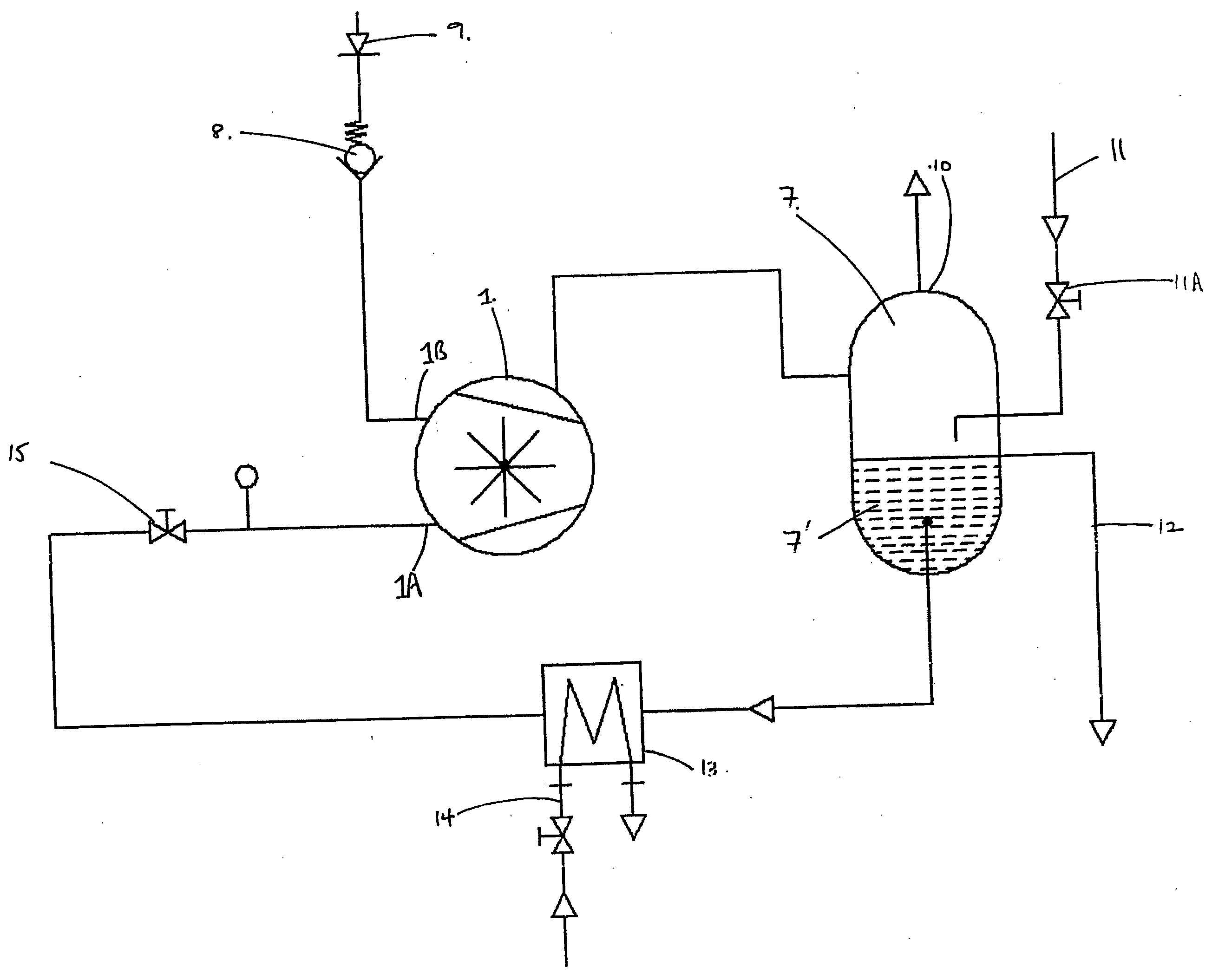
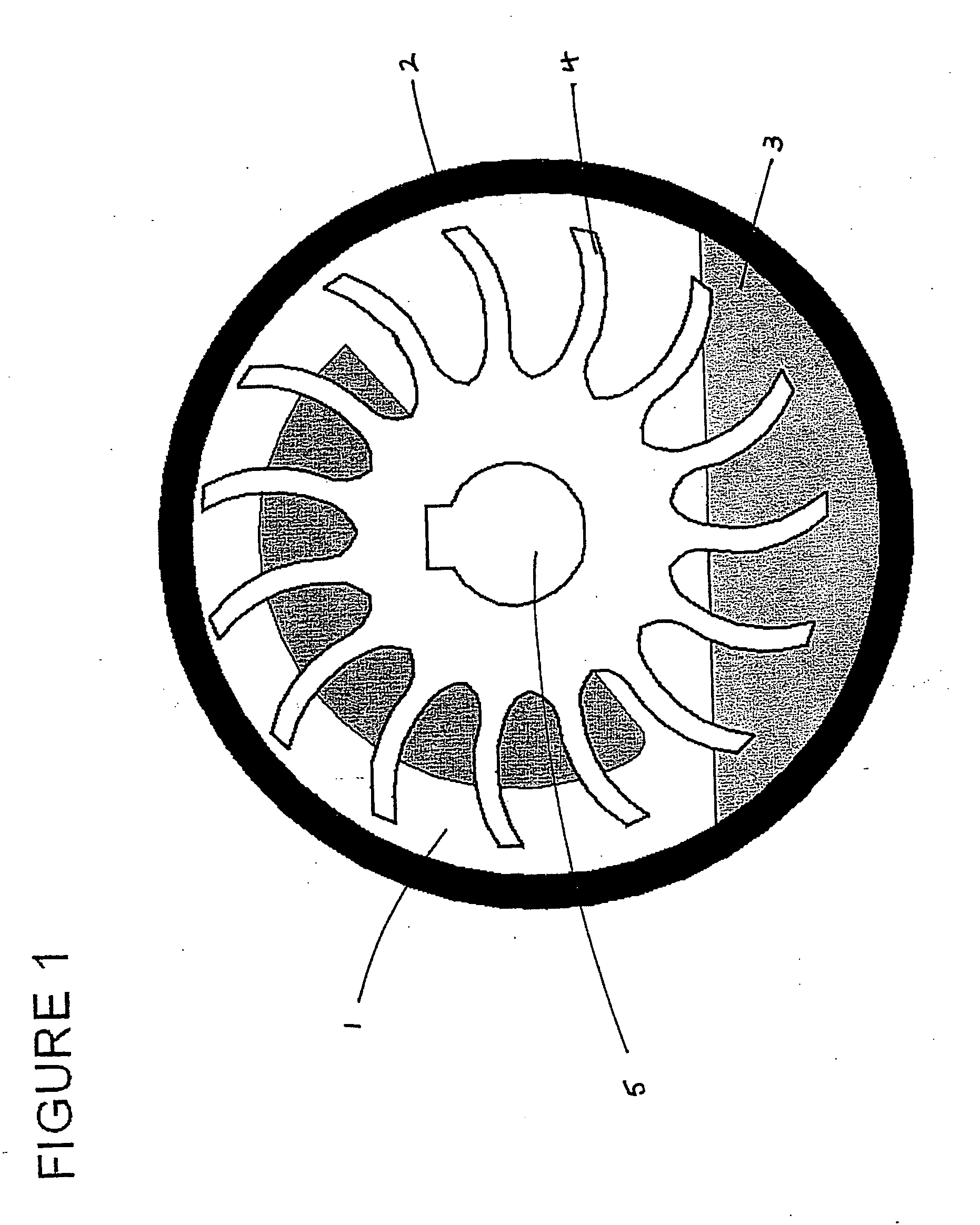
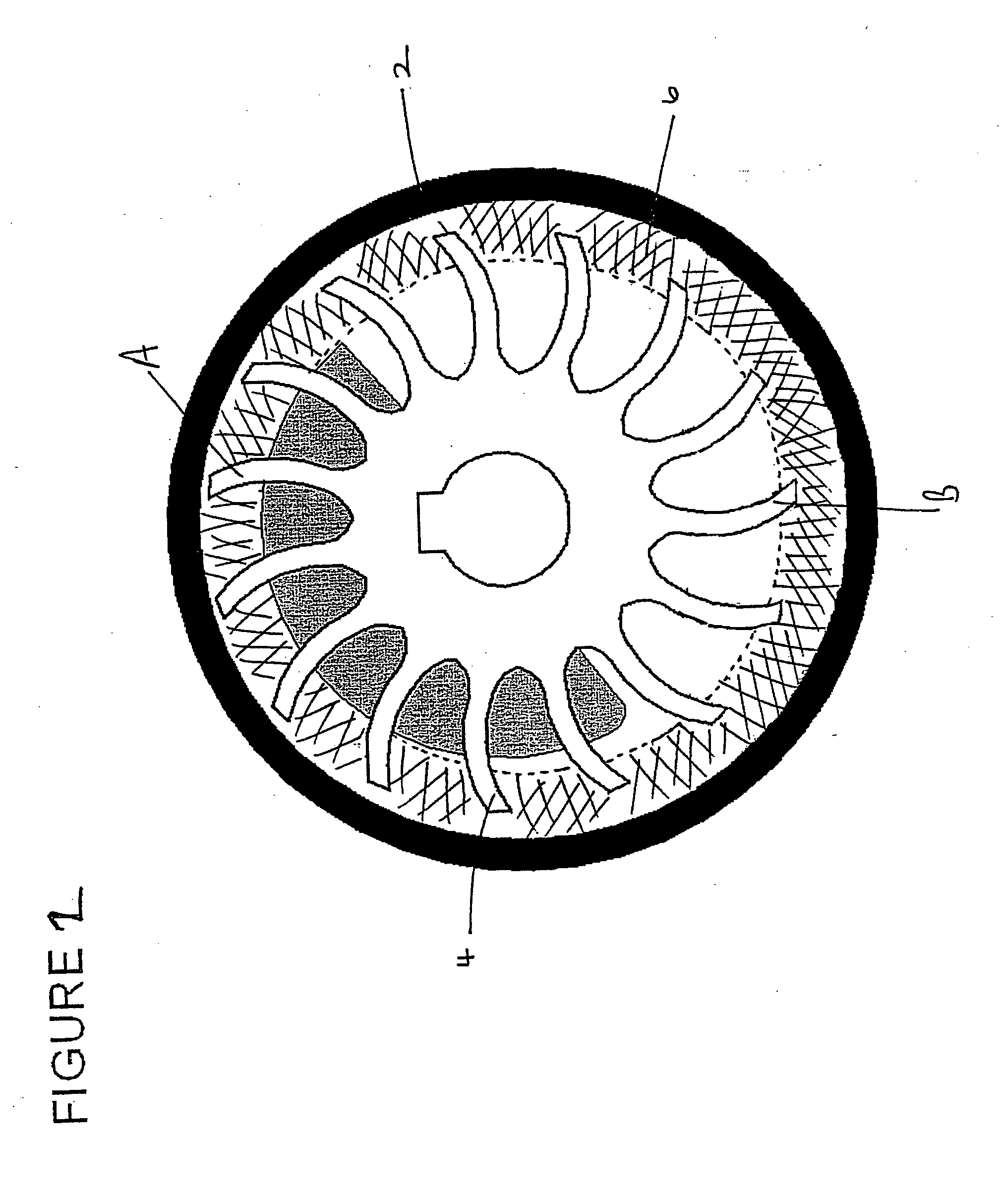
RELATED APPLICATIONS [0001] This application claims priority to U.K. Application No. 0321455.8 filed Sep. 12, 2003, the disclosure of which is hereby incorporated by reference in its entirety. FIELD OF THE INVENTION [0002] This invention relates to a system and method for regulating the volume of barrier fluid in liquid ring vacuum pumps. BACKGROUND OF THE INVENTION [0003] Liquid ring vacuum pumps are suitable for moving fluids. Such fluids will be referred to as “working fluids” throughout the description. The fluid may be a liquid fluid and / or a gaseous fluid. Liquid ring vacuum pumps are commonly used to transfer working fluids in drug, food and plastic extrusion plants. For example, a vacuum pump may be used to evacuate working fluid that has been used to cool hot extruded plastic. In this particular example, the extracted fluid is usually a mixture of air and water. A liquid ring vacuum pump is depicted in FIGS. 1 and 2. FIG. 1 depicts a stationary pump and FIG. 2 depicts a pum...

Claims


Application Information

Patent Timeline
Patent Type & Authority Applications(United States)
IPC IPC(8): F04C19/00
CPCF04C19/004
Inventor EDWARD PHIPPS, JOHN MARKTAHIR, NADIM
Owner AES ENG
Learn More