Microporous filter

Inactive Publication Date: 2005-04-21
ELECTRO SCI IND INC
View PDF5 Cites 9 Cited by
  • Summary
  • Abstract
  • Description
  • Claims
  • Application Information

AI Technical Summary

Benefits of technology

[0007] Stepped holes are advantageous because they cause a reduced drop in pressure that enables passage of material of the desired size through the final, smallest diameter hole.
[0008] In a second preferred embodiment, an imprint patterning toolfoil, which is a sheet of metal with an array of protruding features, is pushed into the flexible membrane to form in it an array of depressions. The UV laser forms the final hole step through the bottom of each of multiple depr

Problems solved by technology

Gases and debris trapped at the bottom of a large aspect ratio hole in

Method used


Image

  • Microporous filter
  • Microporous filter
  • Microporous filter

Examples


example

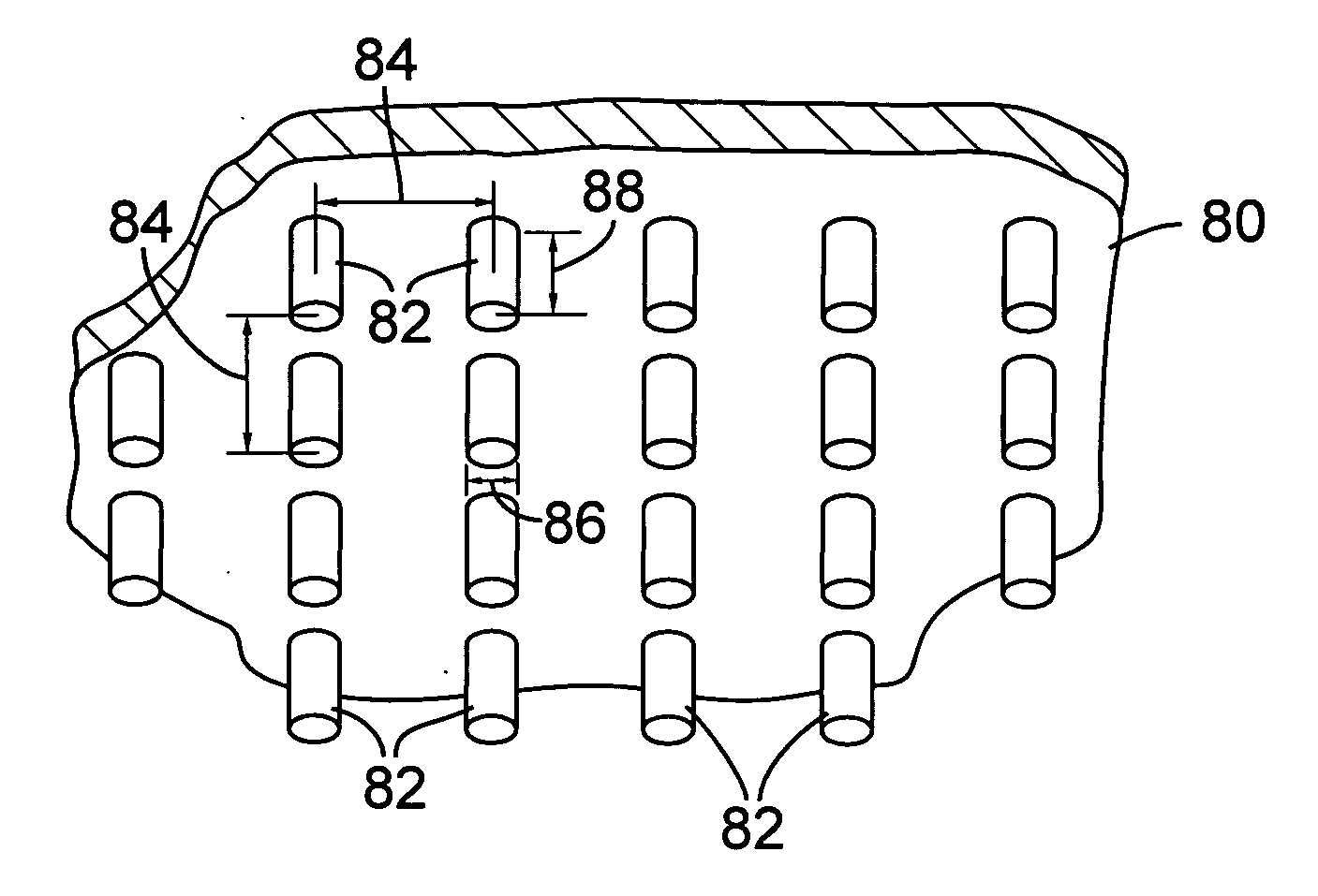
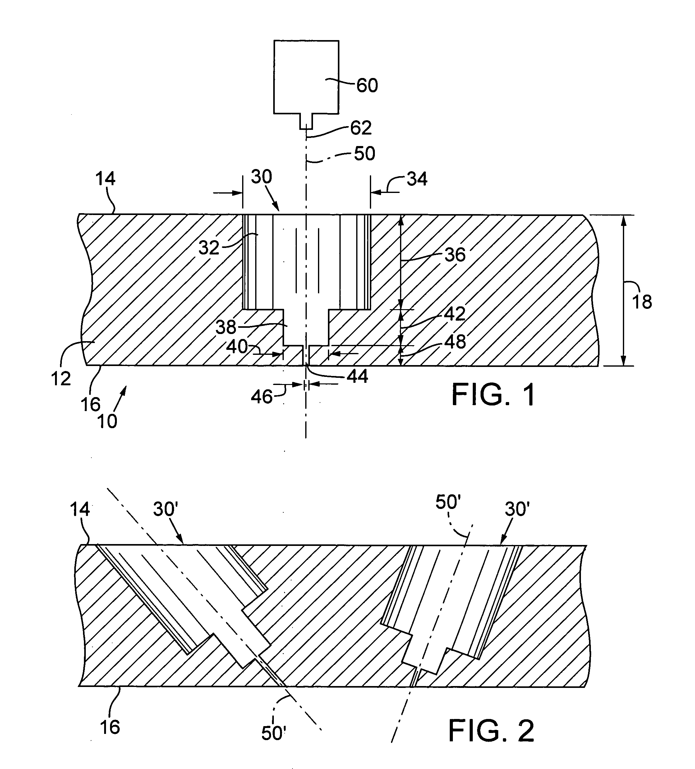
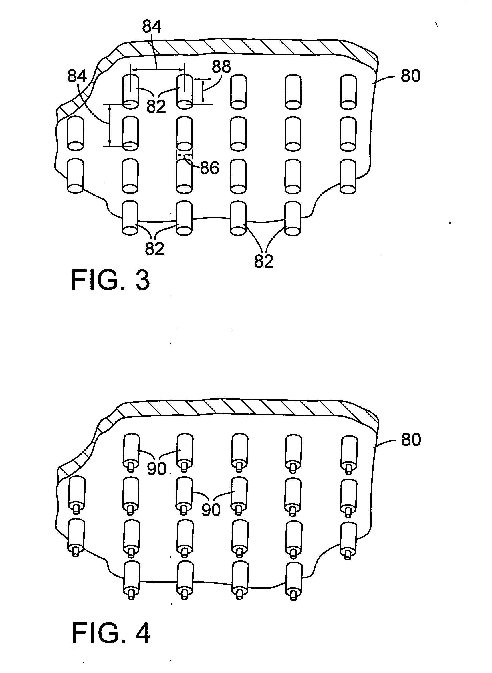
[0019] An array of through holes, each of which having two hole steps, was formed in a 200 μm thick polycarbonate membrane as follows. A 355 nm laser output propagating through a 2× beam expander formed for each hole in the polycarbonate membrane a circular first hole step having a 50 μm diameter and a 180 μm-190 μm depth. The laser beam had a uniform power profile with a 220 mW level at 2 kHz Q-switch rate. A workpiece positioner operating at a 60 mm / sec scan speed moved the laser beam relative to the membrane to repetitively, sequentially scan the hole locations. During the sequential scanning process, the laser beam removed from the hole locations depth-wise portions of membrane material to partly form the first hole steps. The sequential partial removal of portions of membrane material allowed the plasma gases created during the hole step drilling process to escape and thereby ensure formation of high-quality holes. Several iterations of the scanning process sequence were carrie...


PUM

PropertyMeasurementUnit
Wavelengthaaaaaaaaaa
Lengthaaaaaaaaaa
Thicknessaaaaaaaaaa

Abstract

A laser-based drilling technique provides a microporous filter having very small holes with known diameters and locations. One embodiment of the technique entails using a laser beam with one or more uniform spot sizes to form each hole. The laser beam ablates material depthwise for corresponding known distances into a substrate to form a desired number of hole steps in each hole. Another embodiment of the technique entails using an imprint patterning toolfoil to stamp in the substrate depressions of specified diameters and distances that correspond to the hole steps. In both embodiments, a laser beam of Gaussian shape removes the last portion of material to form a very small diameter final hole step.

Description

RELATED APPLICATIONS [0001] This application claims benefit of U.S. Provisional Patent Application No. 60 / 512,007, filed Oct. 15, 2003, and U.S. Provisional Patent Application No. 60 / 542,626, filed Feb. 6, 2004.TECHNICAL FIELD [0002] This invention relates to microporous filters and, in particular, to a microporous filter having small diameter holes of reliable sizes and in known locations. BACKGROUND OF THE INVENTION [0003] Microporous filters are currently made of inherently slightly porous materials such as woven cotton fibers, paper, and woven synthetic fabric. Such filters find applications in the manufacture of pharmaceutical drugs; in industrial fuel cells; and in separating body fluids, chemical particles, and different materials for analysis. The sizes and locations of the holes forming the filter pores vary with the filter material structure. [0004] What is needed is a microporous filter formed of very small, predictable diameter holes placed in known locations and therefo...

Claims


Application Information

Patent Timeline
IPC IPC(8): B01D39/00B01D39/14B01D63/00B01D63/08B01D67/00B01D69/02B23K
CPCB01D63/087B01D67/0032B01D69/02B01D71/36B01D2325/08B01D71/64B01D2323/34B01D2325/021B01D71/50B01D39/00B01D39/14
Inventor SWENSON, EDWARD J.
Owner ELECTRO SCI IND INC
Why Eureka
Try Eureka