Aircraft archway architecture

a technology for aircraft archways and structures, applied in the field of aircraft archways, can solve the problems of reducing affecting the service life of aircraft, so as to reduce the impact of seat configuration, reduce the variation of floor panel design, and reduce the complexity

Active Publication Date: 2005-04-21
THE BOEING CO
View PDF21 Cites 54 Cited by
  • Summary
  • Abstract
  • Description
  • Claims
  • Application Information

AI Technical Summary

Benefits of technology

[0007] In accordance with the present invention, one or more arch-type members (“archways”) are positioned in the cabin of the aircraft. The archways preferably are inverted generally “U-shaped” structures which extend along the inside surfaces of the passenger cabins and have hollow interiors for placement and passage of electrical wires, air conditioning ducts, water lines and the like. The archways are placed at stable locations within the cabin, such as at fixed door locations, so that they will reduce potential impact on seat configurations. The archways provide a path or raceway for the system transport elements particularly between the crown and lower bays of the aircraft.
[0008] The archways also can be positioned at architectural points of interest in the aircraft to help define and establish cabin proportions and also provide logical locations for passage of auxiliary system components. Placement of the archways at door locations provides a passage to run systems at each doorway without interfering with structural intercoastals located between framed bays at the door locations. The archways allow penetration through the floor of the cabin which can be standardized, reducing the variation in floor panel design. In addition, the archways can serve as receptacles for lavatory and gallery monuments, further reducing the complexity associated with integrating those elements into the interior of the aircraft. The archways further can eliminate the need for design close-out seals for outboard monuments.
[0009] The present invention simplifies the installation complexity and eliminates the installation variability associated with installing and running transport elements between the crown and lower bays of the aircraft.

Problems solved by technology

The installation, repair, and modification of the accessory and auxiliary systems, as well as the cabin furnishings, is a considerable expense to aircraft owners and users.
Often, the design and installation of cabin furnishing and auxiliary systems result in modification to the system transport elements, such as electrical wiring, fluid lines, and environmental control system ducts, which result in an increased cost and lead time for delivery of the desired aircraft.
The problem is amplified for those transport systems that pass between the crown and lower bay of the aircraft since this may result in the loss of windows and sidewalls or longer than desired runs to fixed monuments at bulkheads.

Method used


Image

  • Aircraft archway architecture
  • Aircraft archway architecture
  • Aircraft archway architecture

Examples


Embodiment Construction

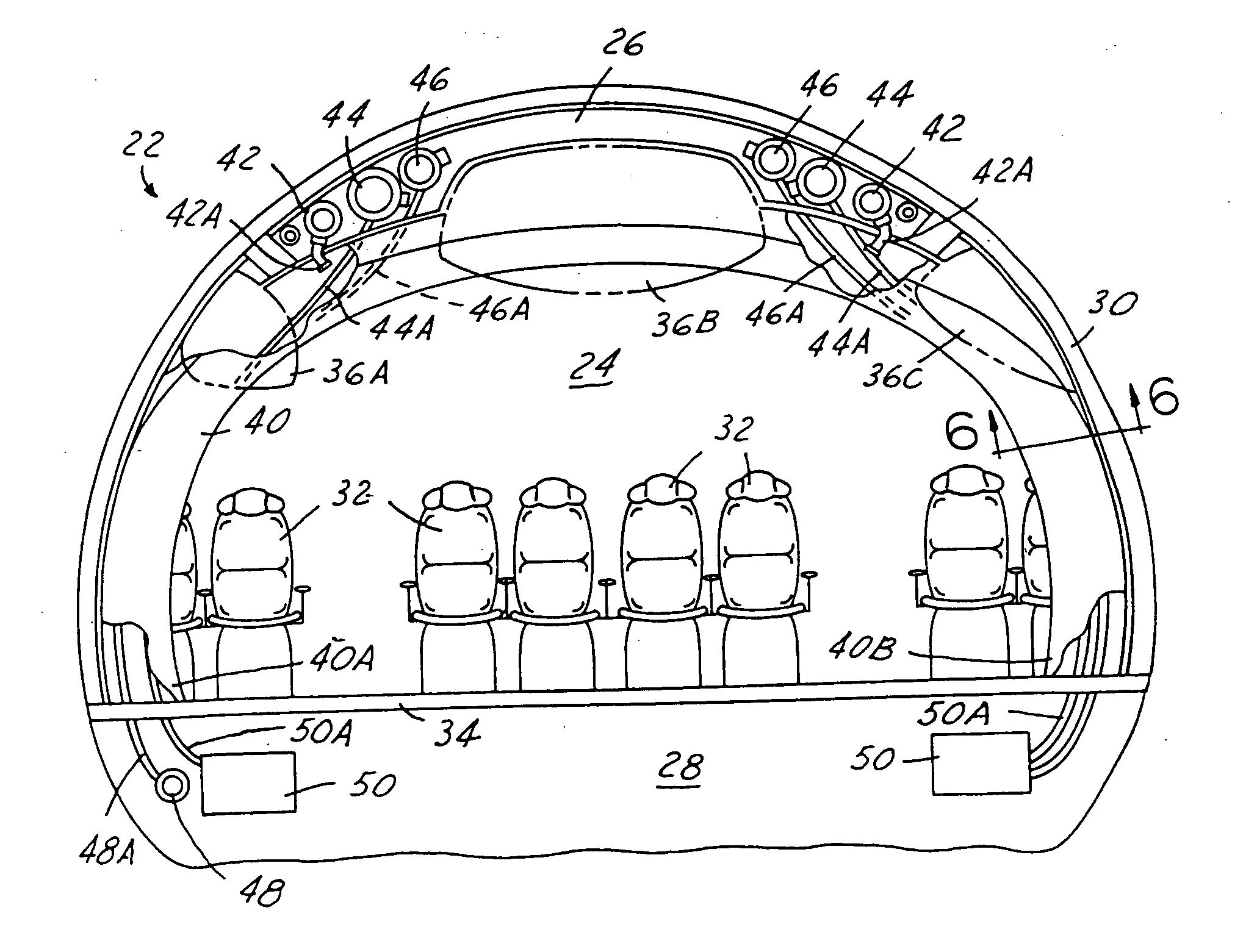
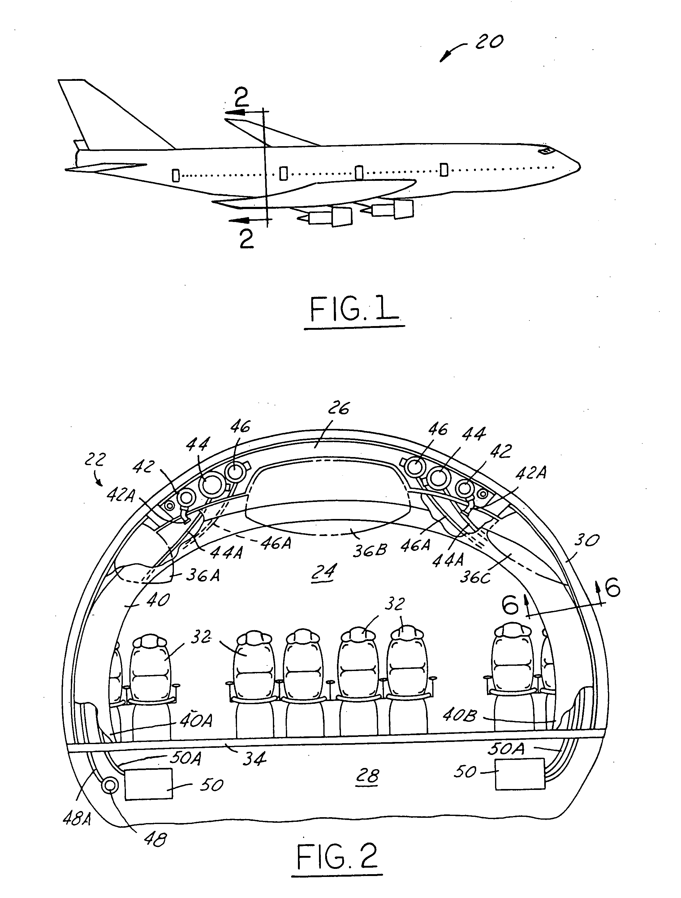
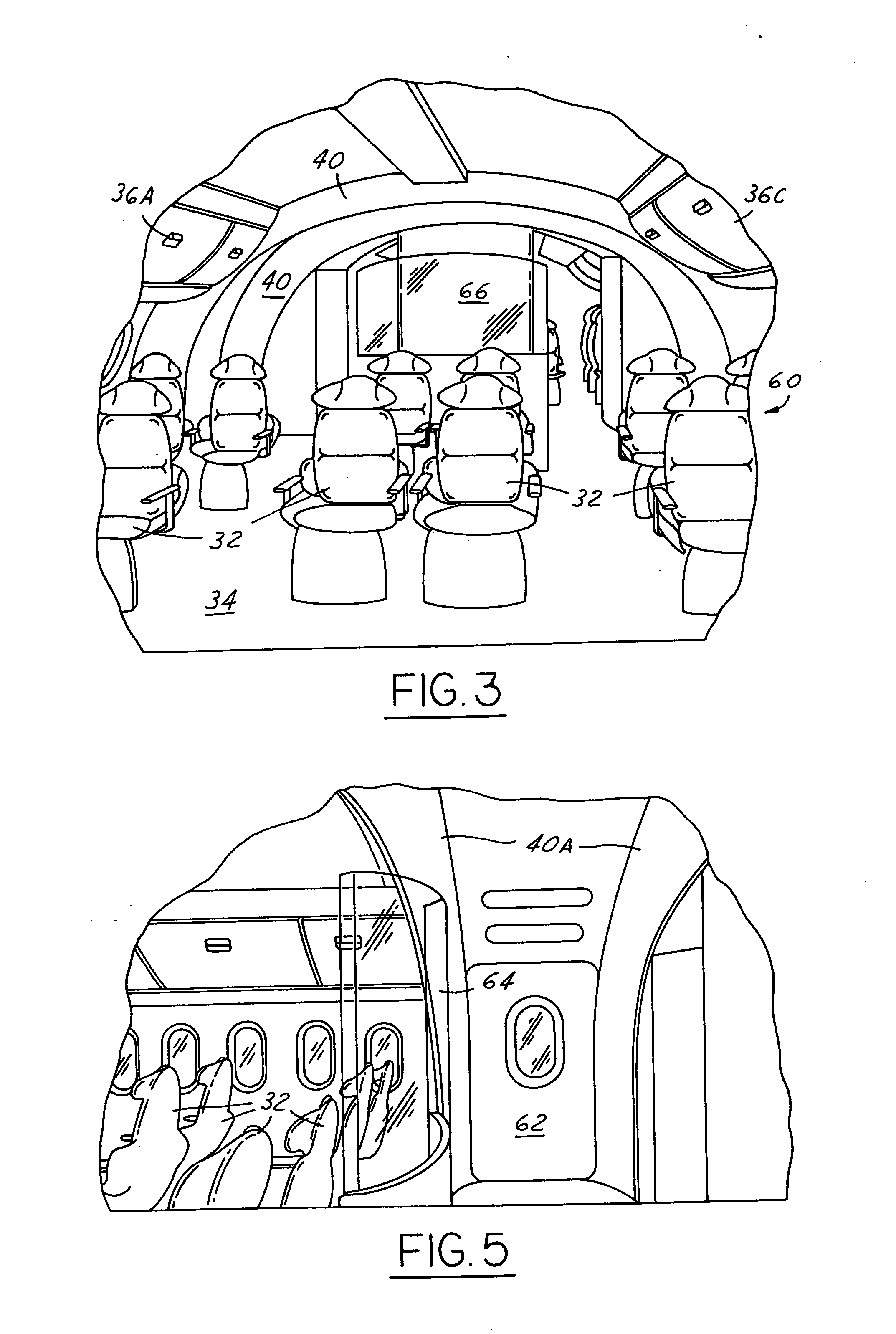
[0020] Efficient interior configuration and modification of airplanes and other aircraft is of value to airline companies and customers by reducing the costs associated with designing and installing cabin furnishings and auxiliary and support systems. Often, these activities will result in modifications to system transport elements, such as electrical wiring, water lines, or environment control system ducts resulting in increased costs and lead time for delivery of the desired aircraft. This problem is amplified for those transport elements that must run or be passed between the airplane crown and the lower lobe or bay, since current design practices result in loss of windows in the sidewalls, or longer than desired runs to fixed monuments at the fore or aft bulkheads.

[0021] The complexity and costs associated with providing for system runs between the crown and lower bays of airplanes and other aircraft has a significant impact on interior architecture, interior flexibility, body ...


PUM


Abstract

An architectural archway for an aircraft. The archways can be positioned individually, or in pairs or other sets along the length of an aircraft fuselage. The archways are used to run or connect various transport elements, such as electrical wiring, water lines, and environmental control system conduits, between the upper crown, lower bay and passenger cabin of the aircraft. The invention simplifies installation complexity and eliminates the installation and variability associated with running transport elements between the various sections of the aircraft.

Description

TECHNICAL FIELD [0001] The present invention relates to architectural structures for aircraft and more particularly to improved structures, cabin furnishing, accessories and auxiliary equipment for aircraft. BACKGROUND OF THE INVENTION [0002] The interior configuration and architecture of aircraft have become relatively standardized today. The arrangements of the passenger seats, bulkheads, lavatories, serving areas, and crew spaces have been developed for convenience and accommodation of both passengers and crew. The passenger compartments are typically divided into two or more sections with bulkheads and lavatories being positioned accordingly. Aisles and passageway spaces are left between sets of seats and at the access doors. [0003] The support lines and conduits for the accessory and auxiliary systems, such as conditioned air, water, hydraulics and electrical systems, are typically positioned in the lower bay below the passenger compartment (cabin) or in the crown or space abov...

Claims


Application Information

Patent Timeline
Patent Type & Authority Applications(United States)
IPC IPC(8): B64C1/06B64C1/12B64D11/00B64D11/02B64D11/06
CPCB64C1/066B64D11/00B64D11/0691B64D11/02B64D2011/0046B64D11/0023
Inventor YOUNG, DAVID A.FRAKER, RICHARDBRAUER, R. KLAUSGUARD, PETER S.
Owner THE BOEING CO
Why Eureka
Try Eureka