Recovery from clipping events in a class D amplifier

a technology of audio amplifier and clipping event, which is applied in the direction of amplifiers, dc amplifiers with modulator-demodulator, and amplifiers with semiconductor devices/discharge tubes, etc., can solve the undesirable effect of amplifier “clipping” referring to the distortion at the amplifier output that occurs, and achieve the effect of substantially reducing the recovery time from a clipping even

Active Publication Date: 2005-04-21
TEXAS INSTR INC
View PDF4 Cites 77 Cited by
  • Summary
  • Abstract
  • Description
  • Claims
  • Application Information

AI Technical Summary

Benefits of technology

[0015] It is therefore an object of this invention to provide a class D amplifier in which the recovery time from a clipping event is substantially reduced.

Problems solved by technology

While the non-zero bias current renders class AB amplifiers theoretically less efficient than class B amplifiers, class AB amplifiers present avoid the crossover distortion of class B amplifiers.
As well known in the art, the undesirable effect of amplifier “clipping” refers to the distortion at the amplifier output that occurs when the input signal to the amplifier exceeds the capability of the amplifier to drive its output.
Of course, the noise resulting from clipping is extremely undesirable, especially in audio systems.
Conventional class D amplifiers therefore present distorted output not only when clipping, but also for a noticeable duration after the input is no longer overdriven into clipping.

Method used


Image

  • Recovery from clipping events in a class D amplifier
  • Recovery from clipping events in a class D amplifier
  • Recovery from clipping events in a class D amplifier

Examples


Embodiment Construction

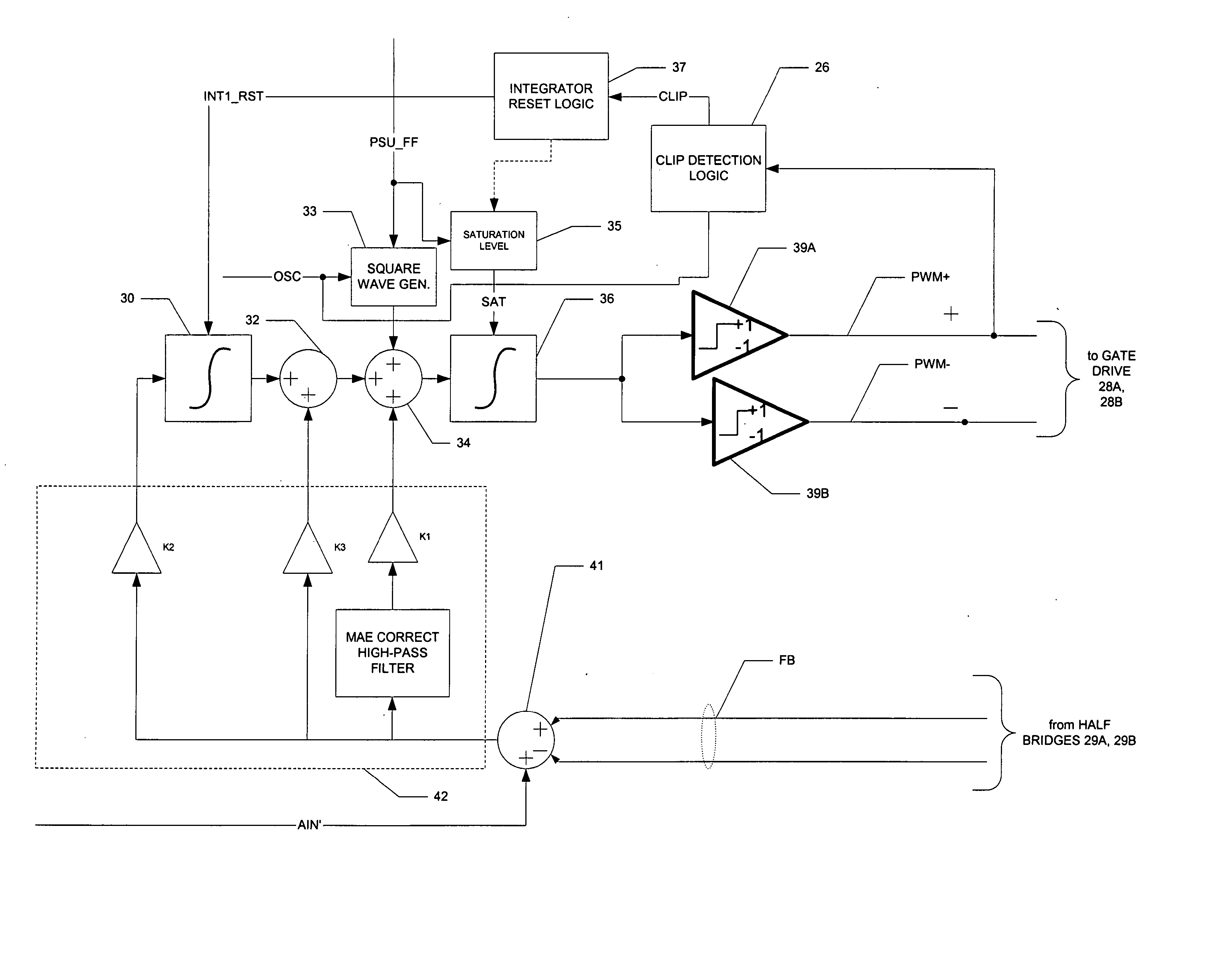
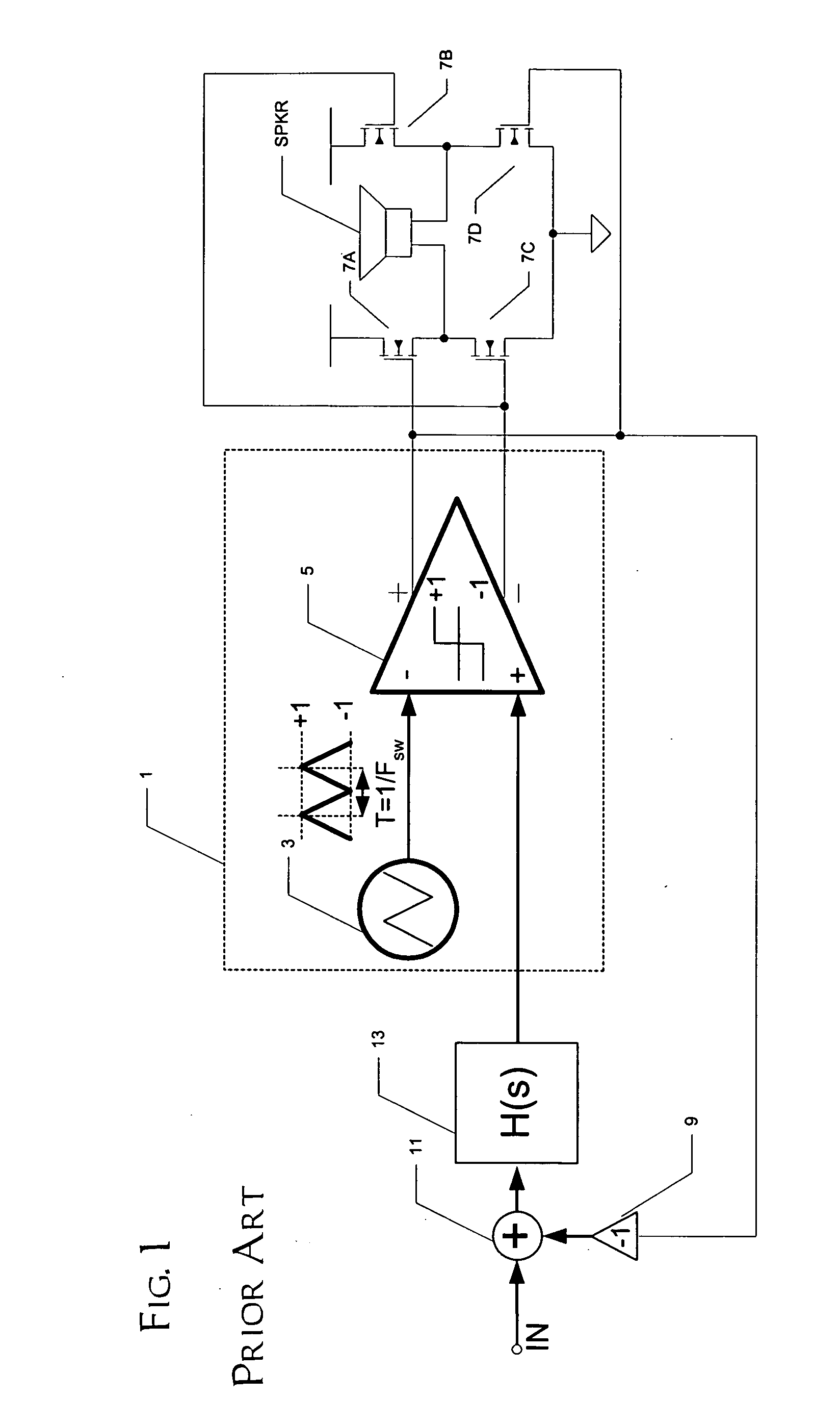
[0028] The present invention will be described in connection with its preferred embodiment, namely as implemented into an audio system, such as an automobile sound system, as it is contemplated that this invention is especially beneficial in such an application. However, it is also contemplated that this invention will be beneficial in many other applications in which class D amplifiers, or pulse-width-modulators, are applicable. Accordingly, it is to be understood that the following description is provided by way of example only, and is not intended to limit the true scope of this invention as claimed.

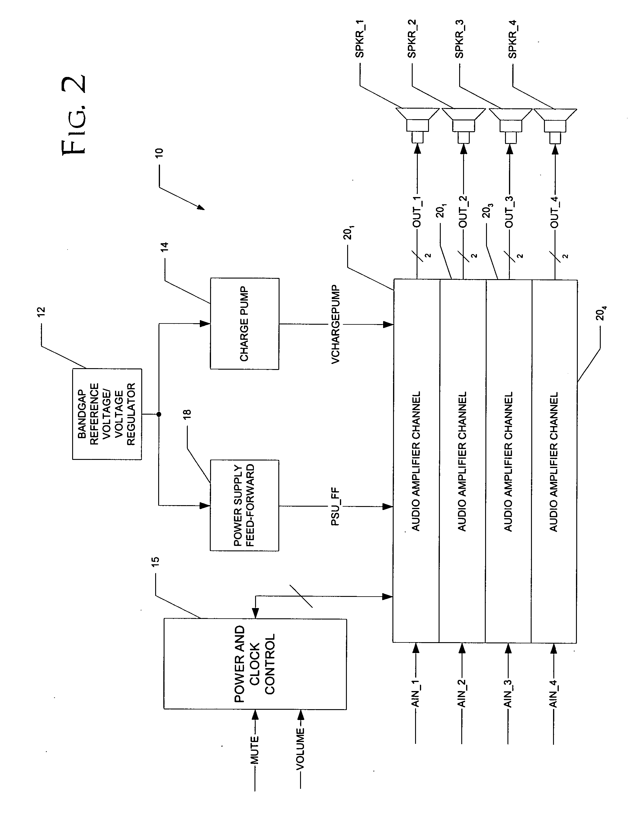
[0029]FIG. 2 illustrates the construction of digital audio amplifier system 10 constructed according to the preferred embodiment of the invention. In this example, system 10 is capable of driving four output audio channels from four separate analog inputs. It is, of course, contemplated that system 10 may drive more or fewer channels, depending upon the system requirements and specif...


PUM


Abstract

A class AD audio amplifier system (10) with improved recovery from clipping events is disclosed. The amplifier system (10) includes multiple audio channels (20), each of which can be constructed to include a pulse-width-modulator (PWM) (24). The PWM modulator (24) includes a pair of comparators (39A, 39B; 52+, 52−) that generate complementary PWM output signals based upon the comparison between a filtered difference signal and a reference waveform. Clip detection logic (26) is provided to detect clipping at the output of the channel (20), preferably by detecting successive edges of the reference waveform without an intervening edge of a PWM output signal. In response to detecting clipping, a first integrator (30; 45) is reset to remove residuals and to eliminate the first integrator (30; 45) from the loop filter of the modulator (24). A saturation level circuit (35) applies a clamping voltage, preferably in both clipping and non-clipping situations, to a second integrator (36; 47). As a result, the loop filter is prevented from entering extreme conditions during clipping, which greatly reduces the clipping recovery time.

Description

CROSS-REFERENCE TO RELATED APPLICATIONS [0001] This application claims priority, under 35 U.S.C. §119(e), of Provisional Application No. 60 / 511,743, filed Oct. 15, 2003.STATEMENT REGARDING FEDERALLY SPONSORED RESEARCH OR DEVELOPMENT [0002] Not applicable. BACKGROUND OF THE INVENTION [0003] This invention is in the field of audio amplifiers, and is more specifically directed to pulse-width modulated class D audio power amplifiers. [0004] As is fundamental in the art, electronic amplifier circuits are often classified in various “classes”. For example, the output drive transistors of class A amplifier circuits conduct DC current even with no audio signal, and the entire output voltage swing is of a single polarity. Class B amplifiers, on the other hand, typically include complementary output drive transistors, driving an output voltage swing including both positive and negative polarity excursions. Class B amplifiers are necessarily more efficient, because both complementary output dr...

Claims


Application Information

Patent Timeline
Patent Type & Authority Applications(United States)
IPC IPC(8): H03F3/217H03F3/38H03F3/68
CPCH03F3/217H03F3/38H03F2200/78H03F2200/66H03F3/68
Inventor RISBO, LARS
Owner TEXAS INSTR INC
Why Eureka
Try Eureka