Reconfigurable interferometer system

a technology of interferometer and system, which is applied in the direction of optical apparatus testing, instruments, optical radiation measurement, etc., can solve the problems of difficult design of null system, high precision of so-called null lens, high labor cost, etc., and achieve the effect of facilitating simultaneous measuremen

Inactive Publication Date: 2005-04-21
ZYGO CORPORATION
View PDF6 Cites 46 Cited by
  • Summary
  • Abstract
  • Description
  • Claims
  • Application Information

AI Technical Summary

Benefits of technology

[0015] Three simultaneous interferograms are formed for purposes of facilitating alignment including one interferogram formed between a reference surface placed in front of the basic optical system and the aspherical reference surface, another interferogram formed between the test surface and the aspherical reference surface, and a third interferogram which is formed between the reference surface placed in front of the basic optical system and the test surface. Computational mea

Problems solved by technology

To fulfill the second precondition, the known technique is to design so-called null lenses, which are high precision, very expensive, and bulky lens systems, which consist of a larger number of spherical lens elements.
In some cases, it is very difficult to design a null system, which m

Method used


Image

  • Reconfigurable interferometer system
  • Reconfigurable interferometer system
  • Reconfigurable interferometer system

Examples


Embodiment Construction

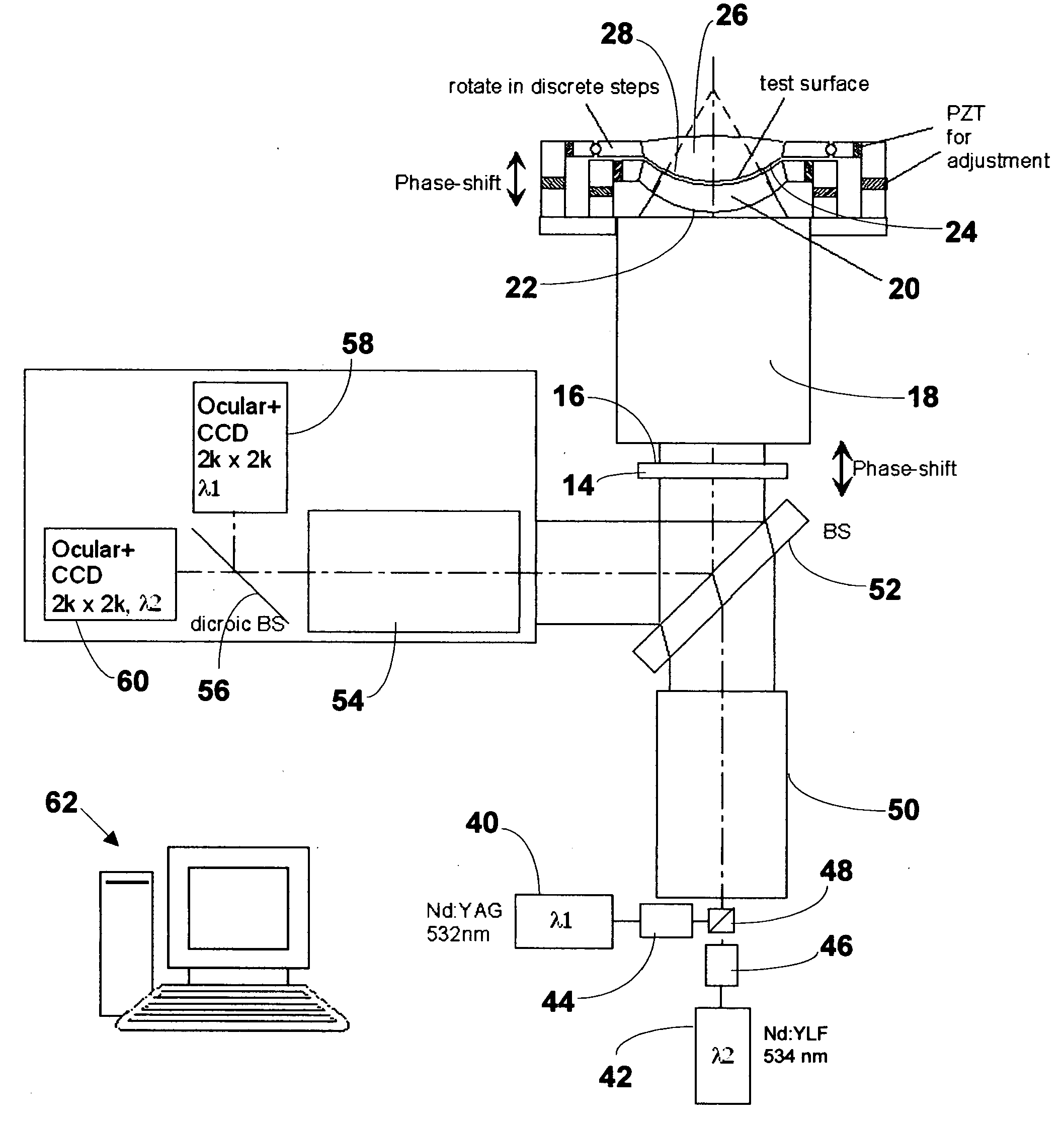
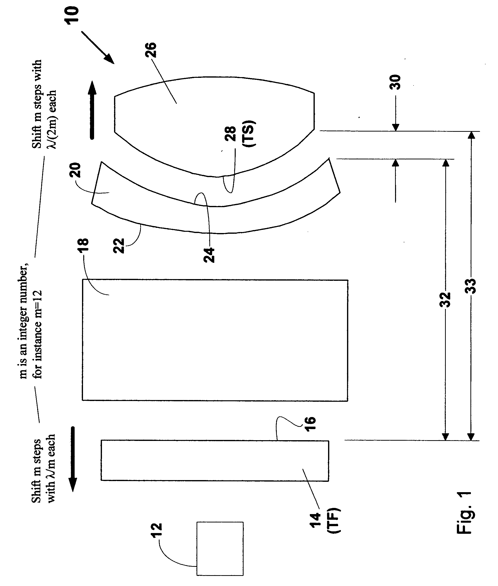
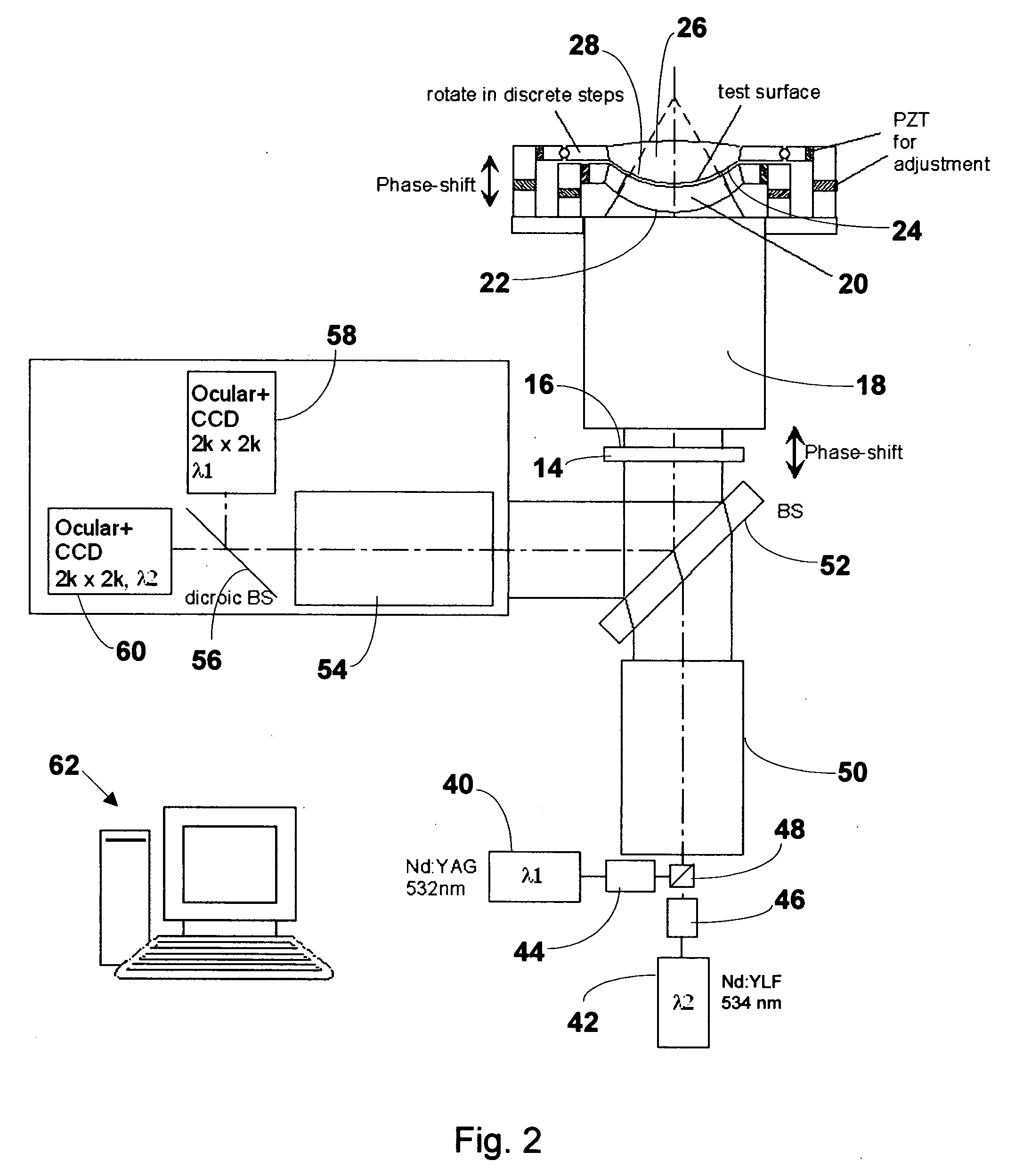
[0026] An interferometer system and methodology will be described for testing spherical or aspherical surfaces. The system is illustrated in simple form in FIG. 1 where is designated generally at 10 and is seen to comprise a coherent light source 12 with preferably two wavelengths, a transmission flat (TF) 14 having a reference surface 16, a lens or basic optical system 18 for generating a convergent (or a divergent) wavefront of known or predetermined shape (mostly but not necessarily of spherical shape) and a reconfigurable (i.e., exchangeable) additional compensation element or component 20 having a compensation surface 22 and carrying a Fizeau reference surface 24 which may be aspherical. The compensation component 20 could be the aplanatic surface of the backside of a lens element, which has a concentric Fizeau reference surface on its front side in the case of testing spheres. In the case of aspherical surface testing, the compensation element could be an aspherical backside o...


PUM


Abstract

Interferometric apparatus and methodology for precisely measuring the shape of rotationally and non-rotationally symmetric optical surfaces comprising an illumination source with two wavelengths, a transmission flat with a reference surface, a basic optical system for producing a wavefront of predetermined shape, a compensation component having an aspheric wavefront shaping surface and an aspheric reference surface. The aspheric shaping surface modifies the predetermined wavefront so that it impinges on the aspheric reference surface with a shape substantially that same as that of aspheric reference surface. For a given aspheric reference surface, the radius or curvature and spacing of the aspheric shaping surface are optimized so that its aspheric departure is no larger than that of the aspheric reference surface. Precise alignment in six degrees of freedom is provided via feedback control.

Description

CROSS REFERENCE TO RELATED APPLICATION [0001] This application claims the benefit, of priority from U.S. Provisional, Application No. 60 / 512,659 filed on Oct. 20, 2003 with the title RECONFIGURABLE INTERFEROMETER SYSTEM, the entire contents of which are incorporated herein by reference.FIELD OF THE INVENTION [0002] This invention in general relates to interferometric metrology of surfaces and more particularly to interferometric apparatus and methods by which optical surfaces can be compared. BACKGROUND OF THE INVENTION [0003] The problem to be solved by the invention is to compare two optical surfaces, spheres or aspheres, which have nominally the same shape. This may done with a Fizeau interferometer system by placing the first surface, called the master calibration surface, in front of the Fizeau reference surface and then making a measurement of the resulting phase difference of the light reflected off the Fizeau reference surface and the master calibration surface. The result i...

Claims


Application Information

Patent Timeline
IPC IPC(8): G01B9/02G01J9/02G01M11/02
CPCG01B11/2441G01J9/02G01M11/025G01B9/02072G01B9/02039G01B9/02007G01B9/02057G01M11/0271
Inventor KUCHEL, MICHAEL
Owner ZYGO CORPORATION
Why Eureka
Try Eureka