Head assembly

a head assembly and assembly technology, applied in the field of head assemblies, can solve the problems of affecting the repair and maintenance of the crdm, affecting and requiring long time, so as to facilitate the disassembly and assembly of the head assembly

Active Publication Date: 2005-04-21
WESTINGHOUSE ELECTRIC CORP
View PDF8 Cites 15 Cited by
  • Summary
  • Abstract
  • Description
  • Claims
  • Application Information

AI Technical Summary

Benefits of technology

[0004] Thus, it is an object of the present invention to provide an improved head assembly that provides both effective CRDM cooling during the fuel cycles and ready access to the CRDMs during the outages. It is a further object to

Problems solved by technology

The many disassembly and re-assembly steps and sub-steps tend to be complex, costly to perform and require long times on critical path schedules in radioactive environments.
However, these newe

Method used


Image

  • Head assembly
  • Head assembly
  • Head assembly

Examples


Embodiment Construction

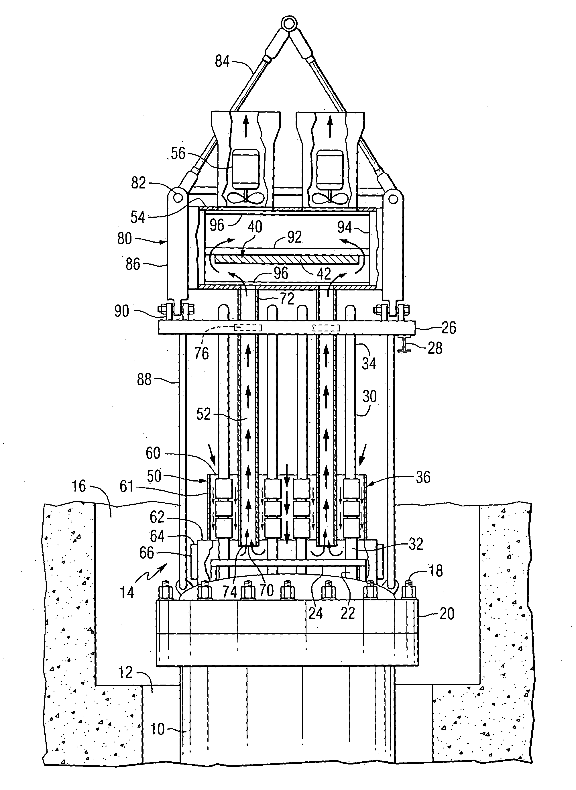
[0014]FIG. 1 depicts a reactor pressure vessel (“RPV”) 10 in a reactor cavity 12 with a head assembly 14 embodying the present invention extending upwardly in one end of a refueling canal 16. The head assembly 14 embodying the present invention may be a new construction or a backfit in an existing plants. FIG. 1 depicts a backfitted RPV 10 in the course of a fuel cycle. At the beginning of the following outage, nuts on closure studs (depicted by stud 18) must be detensioned by devices known as “stud tensioners” so that the RPV closure head 20 and overhead equipment and ductwork can be removed in order to provide unhindered access to fuel assemblies (not shown) in the RPV 10.

[0015] The head assembly 14 as depicted in FIG. 1 generally includes a RPV closure head 20 with a plurality of CRDM penetration nozzles 22. The nozzles 22 are embedded in insulation 24 in the course of fuel cycles. A seismic support platform 26 (supporting a stud tensioner rail 28) is spaced from the RPV closure...


PUM


Abstract

A head assembly for a reactor pressure vessel includes a removable closure head, an array of control rod drive mechanisms, a seismic support platform, a missile shield assembly and a cooling system for drawing atmospheric air across electromagnetic coil stack assemblies. The cooling system includes: a lower shroud surrounding the coil stack assemblies with an end open to the atmosphere around the CRDMs; a plurality of extending internal ducts disposed within the array of CRDMs upwardly to an upper plenum disposed above the seismic support platform and a plurality of fan assemblies disposed on the upper plenum. The missile shield is disposed within the upper plenum. The cooling system effectively cools the coil stack assemblies during fuel cycles and does not hinder access to the CRDMs during an outage. The head assembly has lift legs for transporting either the entire head assembly as an integral unit or the structure above the seismic support platform a subassembly.

Description

BACKGROUND OF THE INVENTION [0001] The invention relates to head assemblies for nuclear reactor pressure vessels (“RPVs”) and more particularly to integrated head assemblies that can be transported as integral units. [0002] Commercial pressurized water nuclear power plants are operated to produce electric power during fuel cycles that extend for about one to two years and then are shutdown for scheduled refueling and maintenance outages that extend for up to about a month or more. At the beginning of these outages, removable RPV closure heads and overhead equipment and cooling air ductwork associated with the RPVs, including control rod drive mechanisms (“CRDMs”), CRDM cooling systems, CRDM seismic support platforms and missile shields (which collectively are known in the industry as the “head assemblies”) must be disconnected and / or removed in order to gain access to the fuel assemblies disposed in the interior portions of the RPVs. Then, at the end of the outages, the head assembl...

Claims


Application Information

Patent Timeline
IPC IPC(8): G21C13/00G21C13/073G21C19/02
CPCG21C13/073G21Y2002/304Y02E30/40G21Y2004/30G21Y2002/40Y02E30/30
Inventor HARKNESS, ALEXANDER W.BALL, MICHAEL G.GONTIS, GREGORY E.
Owner WESTINGHOUSE ELECTRIC CORP
Why Eureka
Try Eureka