Communication system, base station, terminal, communication device, communication management method, control program, and computer-readable recording medium containing the same

a technology of communication management and control program, which is applied in the field of communication system, base station, terminal, communication management method, control program, and computer-readable recording medium containing the same. it can solve the problems of wasting the terminal's communication terminal, foregoing background art, and unable to notify the terminal that the telephone incoming call data has been received

Inactive Publication Date: 2005-04-21
SHARP KK
View PDF7 Cites 108 Cited by
  • Summary
  • Abstract
  • Description
  • Claims
  • Application Information

AI Technical Summary

Benefits of technology

[0015] An object of the present invention is to provide a communication system in which the terminal can suitably set a period at which a beacon signal is received, in accordance with the communication pattern

Problems solved by technology

By the way, in the case where an application operated by the terminal application is, for example, an e-mail reception software, and the terminal accesses to a mail server once every one minute to check whether or not any e-mail message has been received, it is a waste for the terminal to turn on its communication terminal every 100 msec at which the beacon signal is transmitted.
However, the foregoing background art has the following problems.
This makes it impossible to notify to the terminal that telephone incoming call data has been received, if timing is off, upon receiving the incoming telephone call data.
This makes it impossible to respond to the demand for a response in real time, if timing is off.
Therefore, in spite of

Method used


Image

  • Communication system, base station, terminal, communication device, communication management method, control program, and computer-readable recording medium containing the same
  • Communication system, base station, terminal, communication device, communication management method, control program, and computer-readable recording medium containing the same
  • Communication system, base station, terminal, communication device, communication management method, control program, and computer-readable recording medium containing the same

Examples


embodiment 1

[0055]FIGS. 3 and 4 are block diagrams illustrating a schematic arrangement of a wireless communication system 1 of the present embodiment. As shown in FIGS. 3 and 4, the communication system 1 is a system in which a base station 10 performs wireless communications with one or more terminal 30 (30A, 30B, 30C . . . ). The base station 10 relays communications between an external network 2 and the terminal 30. Thus, the wireless communication system 1 includes the base station 10 and the terminal 30. The base station 10 periodically transmits a beacon signal (periodic signal). In accordance with the beacon signal, the terminal 30 is identified from the base station 10. Then, to the identified terminal 30, the presence or absence of data to be transmitted and the period until a transmission of a next beacon signal are notified by using a beacon signal.

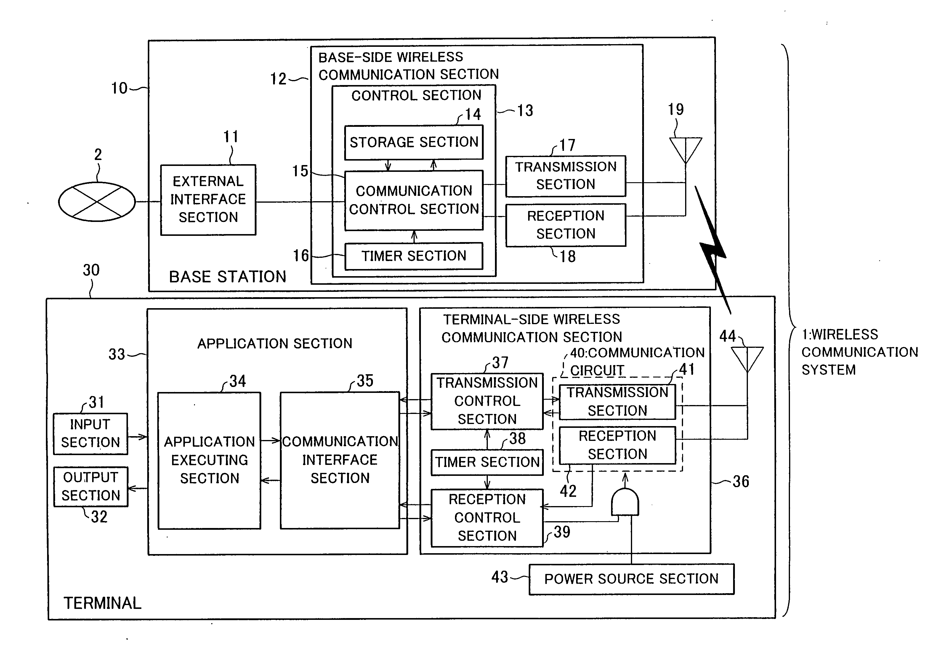
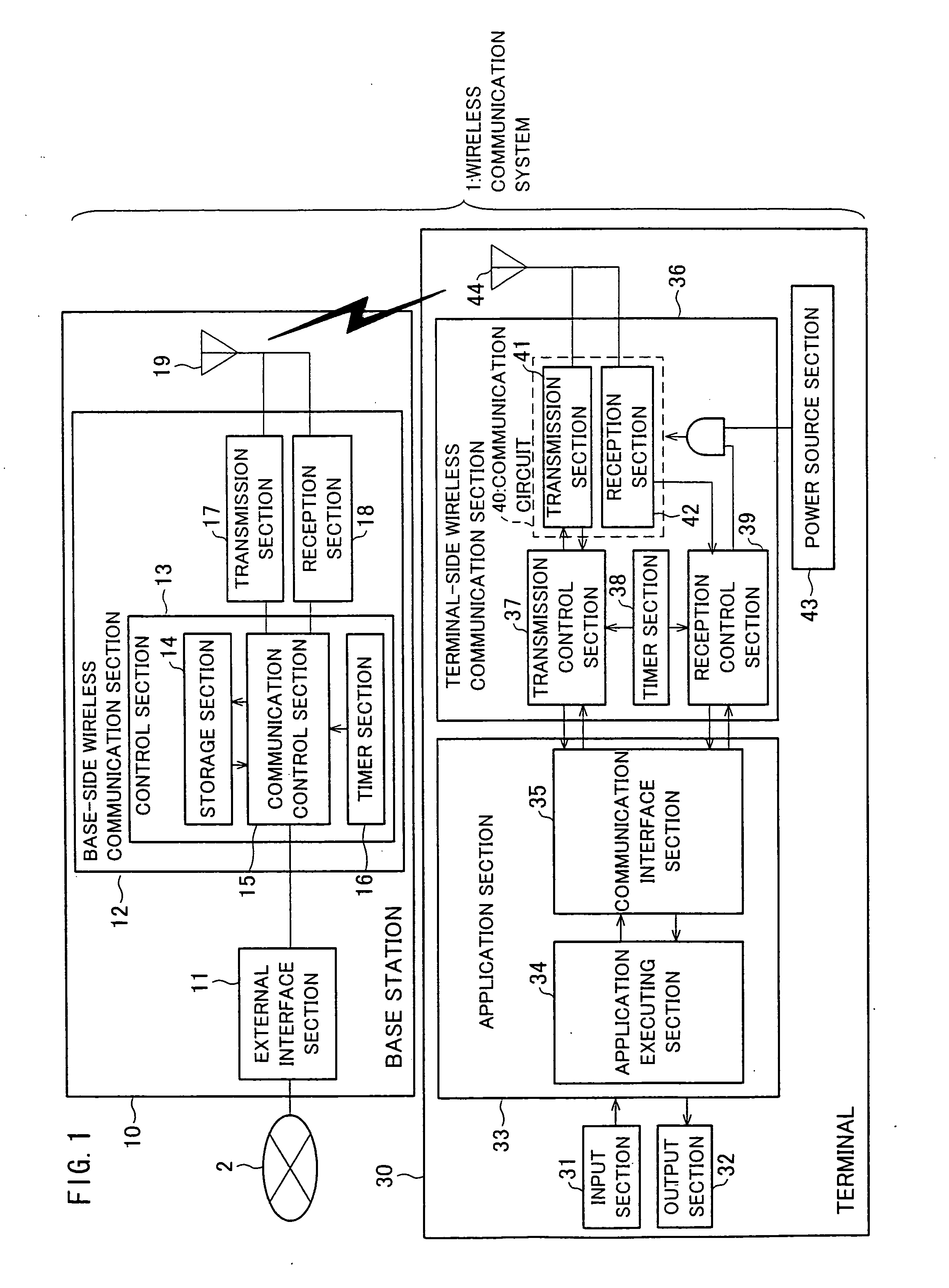
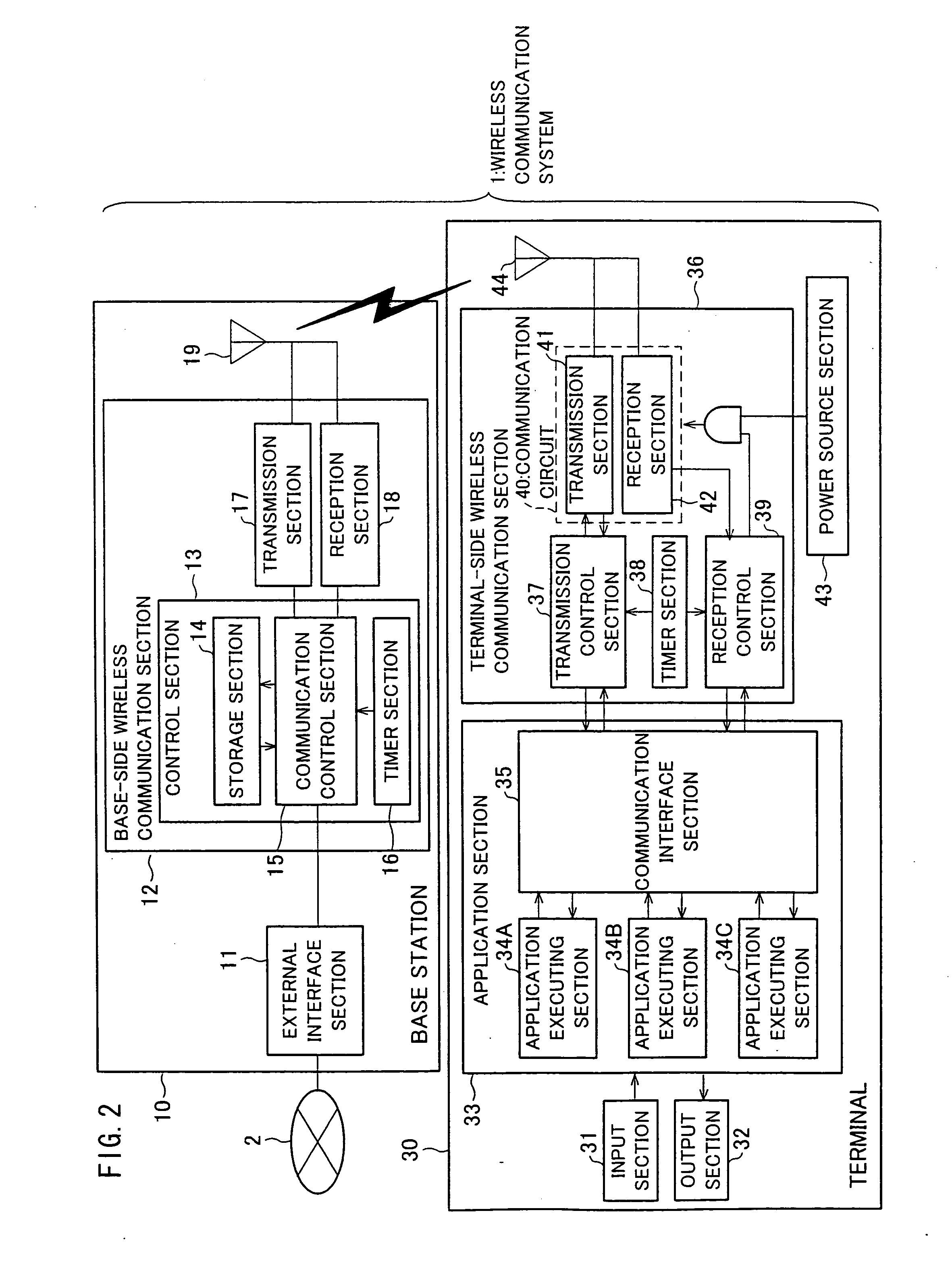
[0056]FIGS. 1 and 2 are functional block diagrams illustrating a detailed arrangement of the wireless communication system 1. FIG. 1 sh...

embodiment 2

[0144] With reference to FIGS. 1 to 4 and 19 to 21, the following describes another embodiment of the present invention. For the purpose of explanation, members whose functions are identical to those of the members described in Embodiment 1 are labeled with identical reference numerals, and explanations of such members are omitted.

[0145] In the wireless communication system 1 of the present embodiment, the terminal 30 dynamically changes its beacon reception period in accordance with a type of an application executed by the terminal 30 and / or a communication property (a communication pattern and / or a state of the application). Therefore, the present embodiment is different from Embodiment 1 in that the beacon period of the base station 10 is not changed. Note that schematic and detailed arrangements of the wireless communication system 1 are as shown in FIGS. 1 to 4.

[0146] More specifically, in the wireless communication system 1 of the present embodiment, the terminal-side wirele...


PUM


Abstract

In a wireless communication system, a terminal is identified by a base station in accordance with beacon signals transmitted periodically from the base station, and to the identified terminal, the presence or absence of data to be transmitted and a period until a transmission of a next beacon signal are notified. A terminal-side wireless communication section in the terminal transmits, to the base station, a request for setting of a period between transmissions of beacon signals. A communication control section in the base station sets the period between transmissions of beacon signals in accordance with the request having been received from the terminal. With this arrangement, the terminal can optimize its period between receptions of beacon signals, thereby keeping OFF power supply to a communication circuit from a power source section until the timing for receiving a beacon signal. This allows the terminal to reduce its power consumption.

Description

[0001] This nonprovisional application claims the benefit of U.S. Provisional Application Ser. No. 60 / 585,528 filed on Jul. 6, 2004, and claims priority under 35 U.S.C. §119(a) on Japanese Patent Application No. 2004 / 151031 filed on May 20, 2004, and Japanese Patent Application No. 2003 / 341877 filed on Sep. 30, 2003, the entire contents of all of which are hereby incorporated by reference.FIELD OF THE INVENTION [0002] The present invention relates to a communication system such as a wireless LAN (Local Area Network), a base station, a terminal, a communication device, a communication management method, a control program, and a computer-readable recording medium containing the same. BACKGROUND OF THE INVENTION [0003] In a wireless LAN realized by a base station and terminals, there is a demand for a minimized power consumption of the terminal. [0004] In a certain kind of wireless LAN, the base station transmits beacon signals periodically to the terminal to notify the terminal of inf...

Claims


Application Information

Patent Timeline
IPC IPC(8): H04B7/005H04B7/26H04L12/28H04W52/02
CPCH04W52/0216Y02B60/50H04W52/0219Y02D30/70
Inventor AOKI, TSUGUHIRO
Owner SHARP KK
Why Eureka
Try Eureka