Methods of treating chronic obstructive pulmonary disease

a technology of obstructive pulmonary disease and which is applied in the field of treating chronic obstructive pulmonary disease, can solve the problems of inability to perform common daily activities, little hope of recovery, and loss of muscle strength of individuals afflicted by copd, and achieve the effect of optimizing the effect of collateral channels

a technology of obstructive pulmonary disease and which is applied in the field of treating chronic obstructive pulmonary disease, can solve the problems of inability to perform common daily activities, little hope of recovery, and loss of muscle strength of individuals afflicted by copd, and achieve the effect of optimizing the effect of collateral channels

US20050085801A1Inactive Publication Date: 2005-04-21BRONCUS TECH

Image

  • Methods of treating chronic obstructive pulmonary disease
  • Methods of treating chronic obstructive pulmonary disease
  • Methods of treating chronic obstructive pulmonary disease

Examples


Embodiment Construction

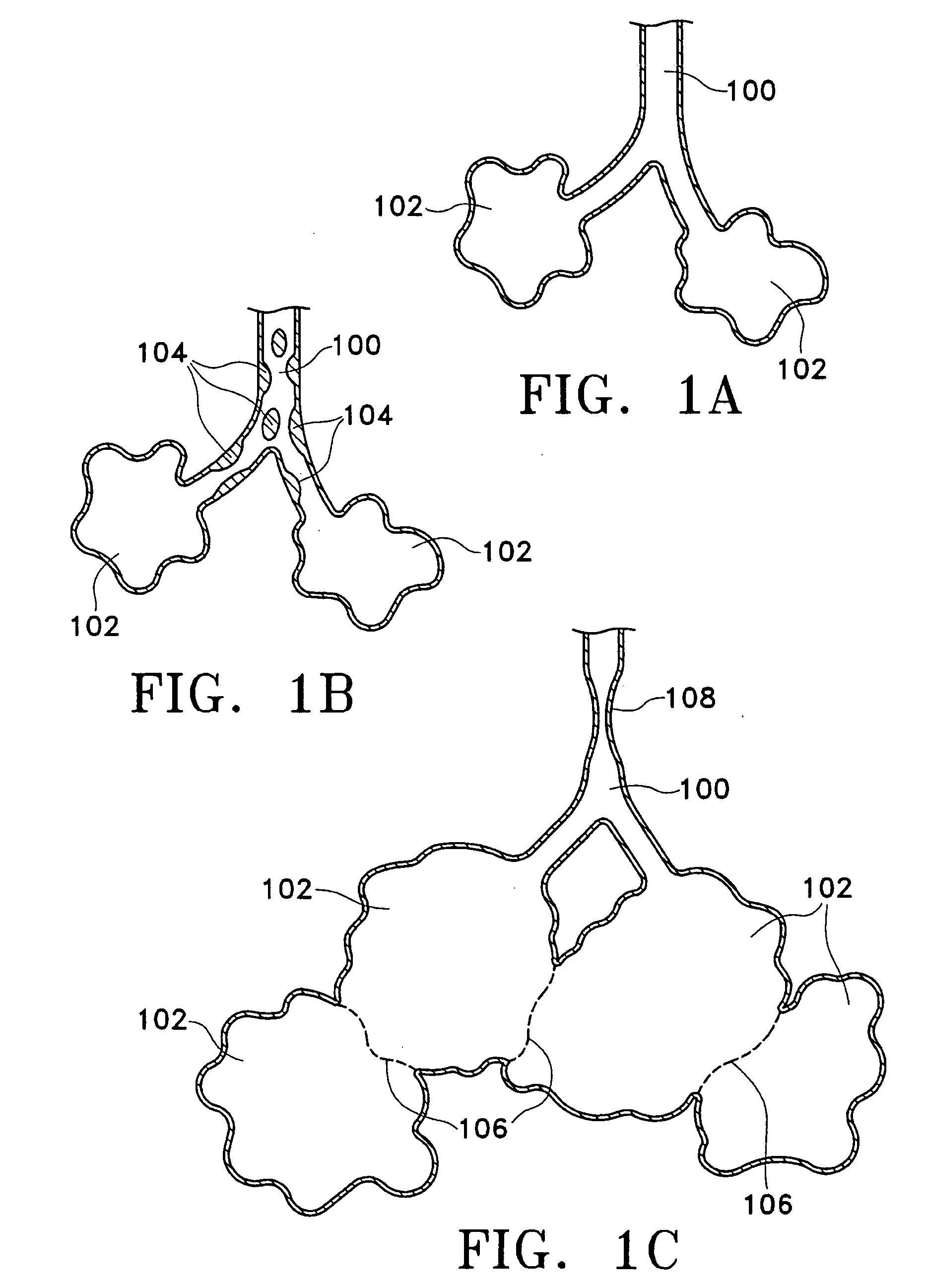
[0058] Prior to considering the invention, simplified illustrations of various states of a natural airway and a blood gas interface found at a distal end of those airways are provided in FIGS. 1A-1C. FIG. 1A shows a natural airway 100 which eventually branches to a blood gas interface 102. FIG. 1B illustrates an airway 100 and blood gas interface 102 in an individual having COPD. The obstructions 104 impair the passage of gas between the airways 100 and the interface 102. FIG. 1C illustrates a portion of an emphysematous lung where the blood gas interface 102 expands due to the loss of the interface walls 106 which have deteriorated due to a bio-chemical breakdown of the walls 106. Also depicted is a constriction 108 of the airway 100. It is generally understood that there is usually a combination of the phenomena depicted in FIGS. 1A-1C. More usually, the states of the lung depicted in FIGS. 1B and 1C are often found in the same lung.

[0059] The following illustrations are examples...


PUM


Abstract

The methods and devices disclosed altering gaseous flow within a lung to improve the expiration cycle of individuals having Chronic Obstructive Pulmonary Disease.

Description

CROSS-REFERENCE TO RELATED APPLICATIONS [0001] This application is a continuation of U.S. patent application Ser. No. 10 / 633,902, filed Aug. 4, 2003, which is a continuation of U.S. patent application Ser. No. 09 / 633,651 filed Aug. 7, 2000 now U.S. Pat. No. 6,692,494, which claims the benefit under 35 U.S.C. § 119(e) of U.S. Provisional Patent Application No. 60 / 147,528 filed Aug. 5, 1999 and 60 / 176,141 filed Jan. 14, 2000, all of which are incorporated in their entirety.FIELD OF THE INVENTION [0002] The invention relates to methods and devices to allow expired air able to pass out of the lung tissue to facilitate both the exchange of oxygen ultimately into the blood and / or to decompress hyper-inflated lungs. The invention also directed to methods and devices to altering gaseous flow within a lung to improve the expiration cycle of an individual, particularly individuals having Chronic Obstructive Pulmonary Disease (COPD). BACKGROUND OF THE INVENTION [0003] The term “Chronic Obstruc...

Claims


Application Information

Patent Timeline
21 Apr 2005
Publication
US20050085801A1
IPC
A61B8/06; A61B8/12; A61B17/02; A61B17/00; A61B17/064; A61B17/08; A61B17/11; A61B17/22; A61B17/24; A61B18/00; A61B18/14; A61B19/00; A61F2/02; A61F2/04; A61F2/20; A61F2/24; A61F2/90; A61F2/92; A61M1/04
CPC
A61B5/489; A61B8/445; A61B8/12; A61B17/064; A61B17/0644; A61B17/08; A61B17/11; A61B17/22
Inventors
COOPER, JOEL D.; LOOMAS, BRYAN