Rod-shaped implant element for application in spine surgery or trauma surgery, stabilization apparatus comprising said rod-shaped implant element, and production method for the rod-shaped implant element

a technology of rod-shaped implants and stabilization apparatuses, which is applied in the field of rod-shaped implant elements for spine surgery or trauma surgery, can solve the problems of limiting the application of this stabilization apparatus, unable to be torsionally stiff, and unsuitable for spinal column use of known joint fixation apparatus, etc., and achieves the effect of reliable fixation in position with such screws

Active Publication Date: 2005-04-21
BIEDERMANN TECH GMBH & CO KG
View PDF17 Cites 674 Cited by
  • Summary
  • Abstract
  • Description
  • Claims
  • Application Information

AI Technical Summary

Benefits of technology

[0025] Preferred embodiments of the rod-shaped implant element of the present invention can absorb one or more of the axial forces, bending forces and torsional forces exerted by the patient. Further, the rod-shaped implant element of the present invention can be used with the known polyaxial or monoaxial bone screws and can be reliably fixed in position with such screws.
[0026] In particular, the rod-shaped imp

Problems solved by technology

However, this stabilization apparatus fails to be torsionally stiff.
In addition, the use of monoaxial pedicle screws limits the application of this stabilization apparatus.
Owing to its complex and voluminous structure, this known joint fixation app

Method used


Image

  • Rod-shaped implant element for application in spine surgery or trauma surgery, stabilization apparatus comprising said rod-shaped implant element, and production method for the rod-shaped implant element
  • Rod-shaped implant element for application in spine surgery or trauma surgery, stabilization apparatus comprising said rod-shaped implant element, and production method for the rod-shaped implant element
  • Rod-shaped implant element for application in spine surgery or trauma surgery, stabilization apparatus comprising said rod-shaped implant element, and production method for the rod-shaped implant element

Examples


first embodiment

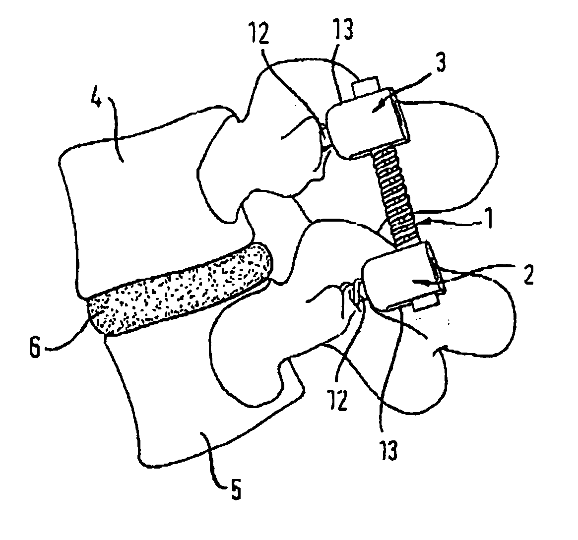
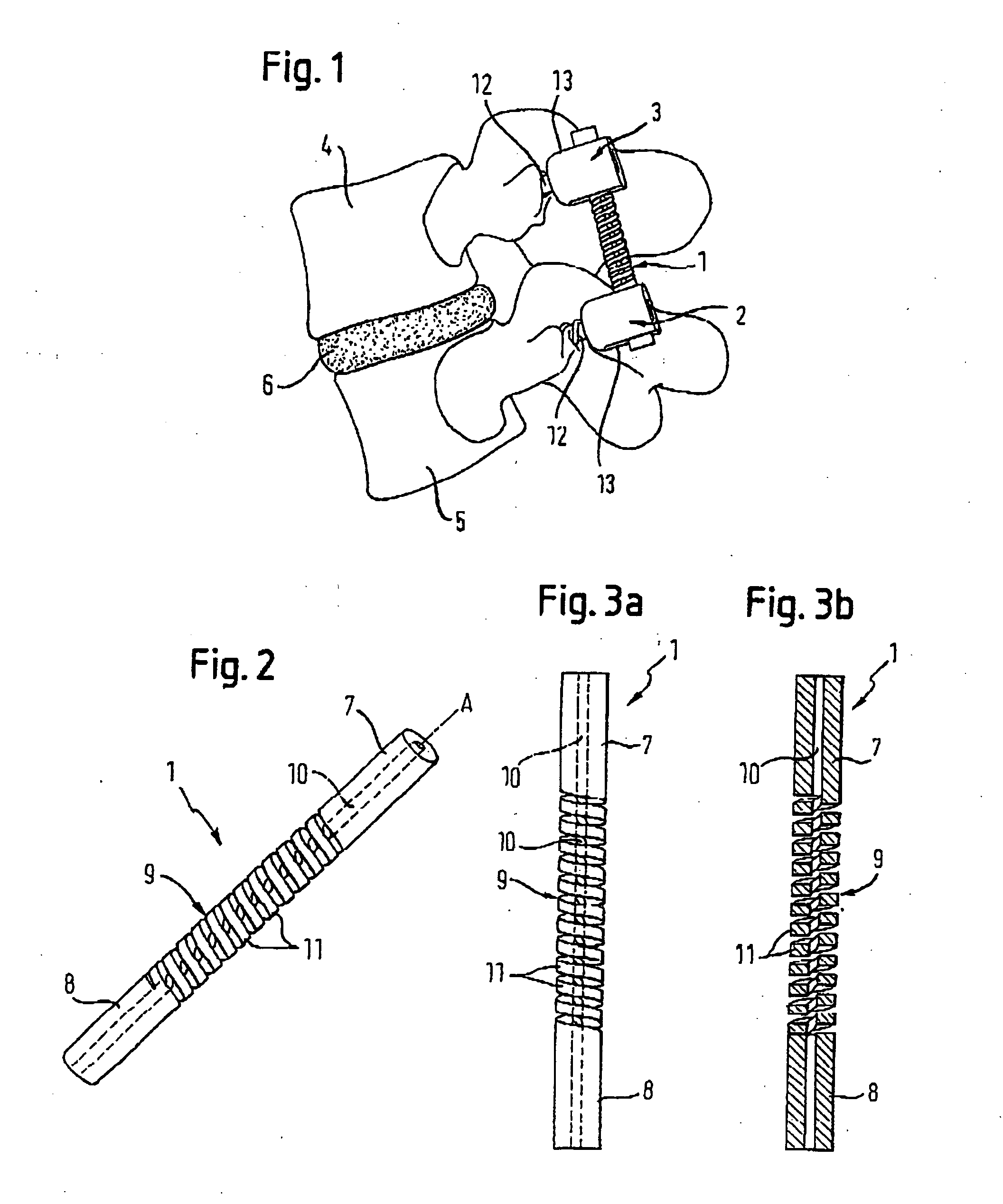
[0057] The rod-shaped implant element 1 according to the invention is designed as a single piece. As shown in FIGS. 2, 3a and 3b, the rod-shaped implant element comprises in a first embodiment a first rigid section 7 that extends across a predefined length from its first end and a second rigid section 8 that extends across a predefined length from its second end as well as a flexible section 9 of predefined length that is provided between the rigid sections 7, 8, with all sections having the same outside diameter. In addition, a coaxial bore 10 of predefined diameter extends through the rod-shaped implant element, The flexible section 9 is designed with a helical slotted opening extending radially from the surface to the coaxial bore 10 with windings 11 of a predefined pitch (a helical groove). The groove can have straight or tap end sides. The height of the windings 11 of the flexible section 9 in the direction of the longitudinal axis A of the rod-shaped implant element, the diame...

third embodiment

[0063]FIGS. 6 and 7 show a rod-shaped implant element 101 according to a This rod shaped implant element is different from the rod-shaped implant elements 1, 100 of the preceding embodiments in that the flexible section 900 that is provided between the rigid sections 7, 8 comprises two regions 901 that are offset by 180 degrees in relation to each other and are shaped towards the axis of the rod in a concave manner in an arc extending along the axis. The length L of the regions 901 in direction of the rod axis is no more than equal to the length of the flexible section 901, and the bending radius is such that the windings of the helical slotted openings are not interrupted. Due to this form, the flexible section 900 has a “waisted” form (i.e., like the waist of a person) in a direction B that is perpendicular to the rod axis A, thus possessing less stiffness in this direction. This provides an oriented stiffness that is appropriate for certain applications.

[0064] The operation is i...

fourth embodiment

[0065] In a fourth embodiment that is shown in FIG. 8 and 9, the rod-shaped implant element 102 comprises a cylindrical core 110 that extends in coaxial direction through the flexible section 902 and possesses a specific bending flexibility. The diameter of the core 110 is dimensioned such that the core 110, after having been pushed into the bore 10, is truly secured in the latter. Preferably, the core is made of the same material as the rod-shaped implant element, but it may also consist of a second biocompatible material such as, for example, a flexible plastic material.

[0066] In a modified form, the core 110 is connected to the rigid sections 7, 8 and to the windings of the helical slot flexible section 902 in a single piece. For example, when a core of the same material is desired, it also can be provided by omitting the coaxial bore in the manufacturing of the rod-shaped implant element. As compared with the first embodiment, the core 110 causes a higher bending stiffness of th...


PUM


Abstract

A rod-shaped implant element (1, 100, 101, 102, 300) is disclosed for the connection of bone anchoring elements, Each bone anchoring element has an anchoring section (12) to be anchored in the bone and a receiver member (13) to be connected to the rod-shaped implant element The rod-shaped implant element has at least one rigid section (7, 8) that is configured to be placed in the receiver member (13). It also has a flexible section (9, 90, 900, 902) that is adjacent to the rigid section. The flexible section and the rigid section are formed in one piece. Also disclosed is a stabilization apparatus using a rod-shaped implant element and at least two of the bone anchoring elements. The stabilization apparatus can limit the movement of two vertebrae or parts of a bone in relation to each other in a defined manner.

Description

CROSS REFERENCE TO RELATED APPLICATIONS [0001] This application claim priority from U.S. Provisional Application Ser. No. 60 / 512,113 filed Oct. 17, 2003 and from U.S. Provisional Application Ser. No. 60 / 518,469 filed Nov. 7,2003.FIELD OF THE INVENTION [0002] The present invention relates to a rod-shaped implant element for application in spine surgery or trauma surgery, a stabilization apparatus comprising said rod-shaped implant element, and a production method for such a rod-shaped implant element In particular, the rod-shaped implant element has an integral flexible section. BACKGROUND OF THE INVENTION [0003] EP 0 669 109 B1 discloses a stabilization apparatus for stabilizing neighboring thoracic; vertebrae, which comprises two monoaxial pedicle screws and a strap that is fixed in the receiver members of each pedicle screw by means of a clamping screw and which contains a support element that is mounted on the strap and is designed as a pressure-resistant body. However, this stab...

Claims


Application Information

Patent Timeline
IPC IPC(8): A61B17/58A61B17/00A61B17/60A61B17/64A61B17/70A61F2/44
CPCA61B17/645A61B17/7004A61B17/7028A61B2017/564A61B2017/606A61F2/4465A61B17/7037
Inventor HARMS, JURGENBIEDERMANN, LUTZMATTHIS, WILFRIED
Owner BIEDERMANN TECH GMBH & CO KG
Why Eureka
Try Eureka