Systems and methods for providing network security with zero network footprint

a technology of network security and system and method, applied in the field of network security, can solve the problems of invisible and unavailability for direct attacks, and achieve the effect of relatively easy installation

Inactive Publication Date: 2005-04-21
TREND MICRO INC
View PDF3 Cites 10 Cited by
  • Summary
  • Abstract
  • Description
  • Claims
  • Application Information

AI Technical Summary

Benefits of technology

[0007] One technical advantage is that installation is relatively easy since there is no need to reconfigure the user's network to include a security device having an address. This then allows for “hot” installation, relocation, and / or removal, if desired.

Problems solved by technology

The system and method does not have a physical address that is identifiable to any internal or external device, and is thus invisible and not available for direct attacks.

Method used


Image

  • Systems and methods for providing network security with zero network footprint
  • Systems and methods for providing network security with zero network footprint
  • Systems and methods for providing network security with zero network footprint

Examples


Embodiment Construction

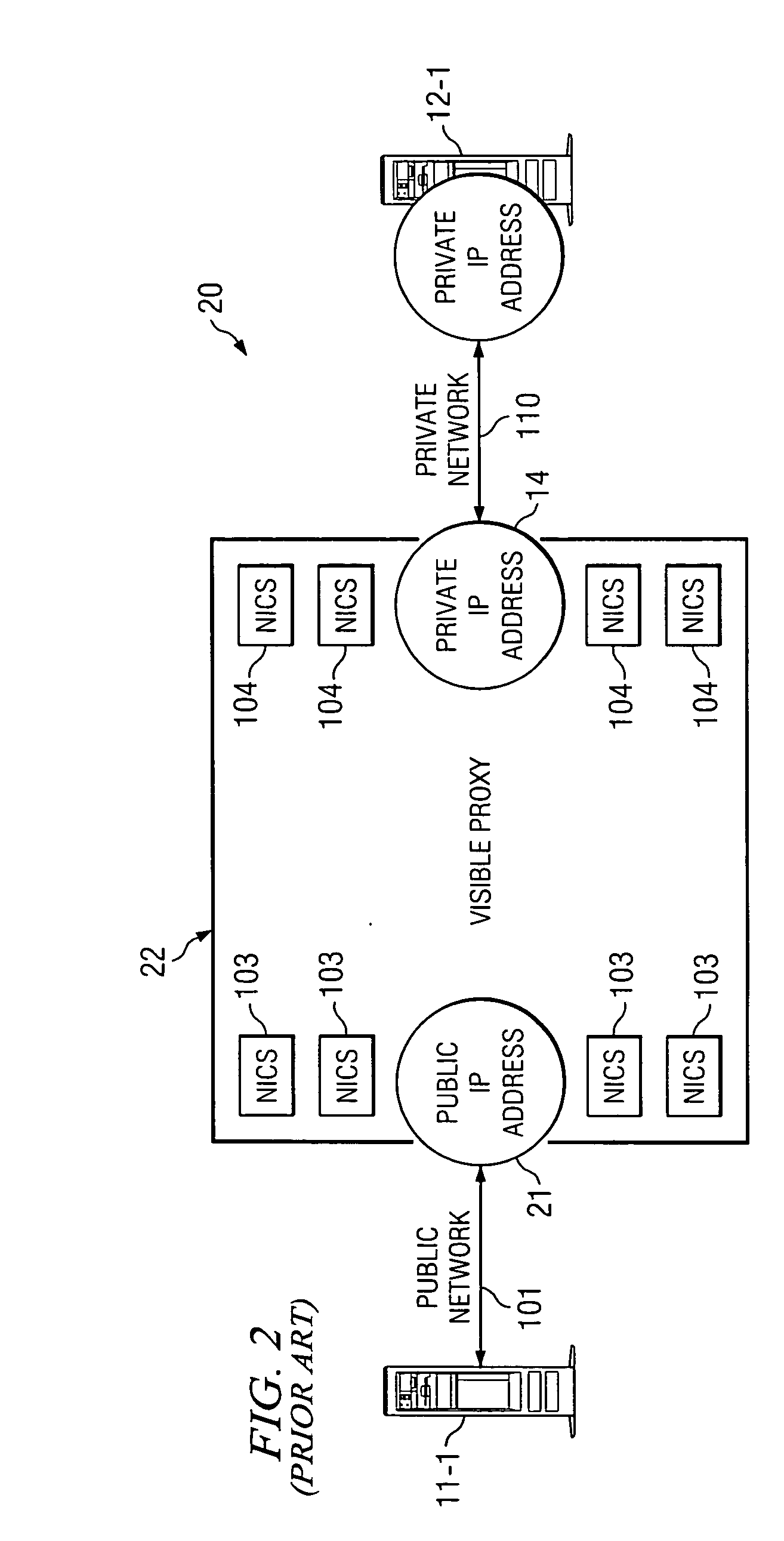
[0012] Before beginning the detailed description of the operational aspects of the system and method of this invention, it might be helpful to review the operation of a prior art system 20 with respect to FIG. 2.

[0013] In such a system, a sending device, such as server 11-1, would send a packet, or packets, of data over public network 101 to a specific location. The specific location would have public IP address 21. Public IP address 21, in turn, will be the input to proxy 22 which includes within it information pertaining to addresses within the protected network.

[0014] Note that since proxy 22 IP address is known to server 11-1 it is called a visible proxy. Visible proxy 22, in turn, then as discussed, forwards this information to private IP address 14 over private network 102 to any one of the number of private IP addresses which in effect are at the destination, devices at such at the destination server 12-1.

[0015] Physical proxy 22 operates to remove from the incoming data s...


PUM


Abstract

The present invention is directed to a system and method which essentially hides the protection device from the public network, while still allowing the device to perform security inspections. The system and method, in one embodiment, operates in the promiscuous mode and does not have a physical address that is identifiable to any internal or external device, and is thus not available for direct attacks. Using this approach, every data packet flowing into the protected system can be viewed and actions taken to protect the network while the device remains free of the threat of a direct attack.

Description

CROSS-REFERENCE TO RELATED APPLICATIONS [0001] The present application is related to filed, co-pending, and commonly assigned U.S. patent application Ser. No. 09 / 572,112, filed on May 17, 2000, entitled “INTELLIGENT FEEDBACK LOOP PROCESS CONTROL SYSTEM”; U.S. patent application Ser. No. 09 / 875,319, filed on Jun. 6, 2001, entitled “SYSTEM AND METHOD FOR TRAFFIC MANAGEMENT CONTROL IN A DATA TRANSMISSION NETWORK”; and U.S. patent application Ser. No. 10 / 078,386, filed on Feb. 20, 2002, entitled “SYSTEM AND METHOD FOR DETECTING AND ELIMINATING IP SPOOFING IN A DATA TRANSMISSION NETWORK” the disclosures of which are all hereby incorporated herein by reference.TECHNICAL FIELD [0002] This invention relates to network security and more particularly to a system and method for providing network security without leaving a networking footprint. BACKGROUND OF THE INVENTION [0003] The problem in the industry for security products and security appliances platforms is their vulnerability to hackers...

Claims


Application Information

Patent Timeline
IPC IPC(8): G06FG06F11/30H04L29/06H04L29/12
CPCH04L29/12783H04L63/1491H04L63/1441H04L61/35
Inventor CAVANAUGH, ROBERT E.
Owner TREND MICRO INC
Why Eureka
Try Eureka