Disk array device having spare disk drive and data sparing method

a technology of disk array device and spare disk drive, applied in the field of disk, can solve the problems of large disk drive capacity, high probability of multiple disk failure, and high reliability and performance, and achieve the effect of reducing the risk of data loss

a technology of disk array device and spare disk drive, applied in the field of disk, can solve the problems of large disk drive capacity, high probability of multiple disk failure, and high reliability and performance, and achieve the effect of reducing the risk of data loss

US20050086557A1Active Publication Date: 2005-04-21RAKUTEN GRP INC

Image

  • Disk array device having spare disk drive and data sparing method
  • Disk array device having spare disk drive and data sparing method
  • Disk array device having spare disk drive and data sparing method

Examples


Embodiment Construction

[0038] An embodiment of a disk array device in accordance with the present invention will be described hereinafter.

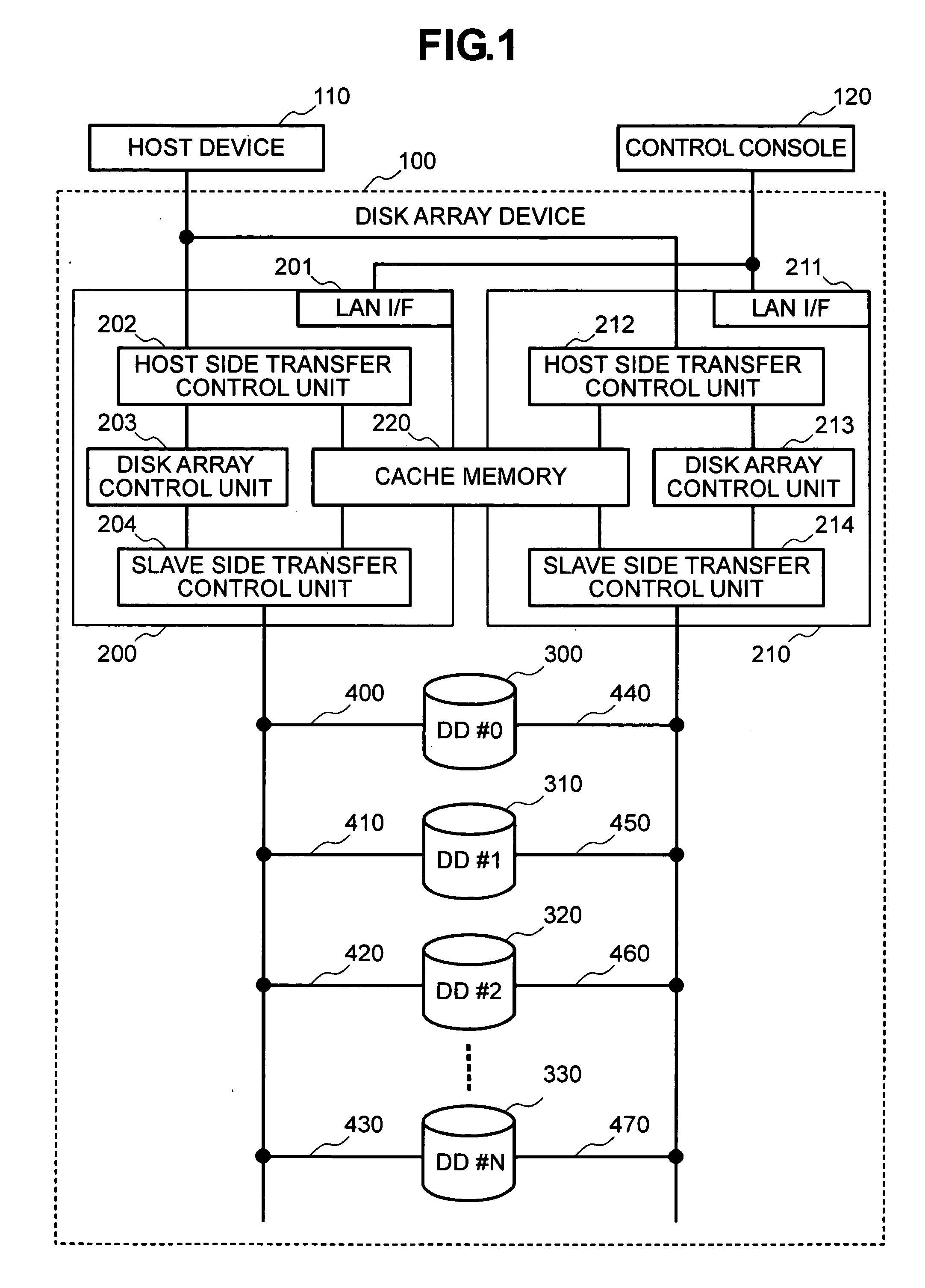
[0039]FIG. 1 shows a computer system, which uses a disk array device in accordance with an embodiment of the present invention, and the internal structure of this disk array device.

[0040] As shown in FIG. 1, a disk array device 100 is connected to a host device 110, such as a host computer, and includes plural hard disk drives (drive numbers #0 to #N) 300 to 330 and one or two or more controllers 200 and 210. In addition, this disk array device 100 includes a control console 120 for carrying out the operation and setting of the disk array device 100. The controllers 200 and 210 are connected to the control console 120 via LAN interfaces 201 and 211, respectively.

[0041] The controllers 200 and 210 respectively include: host side data transfer control units 202 and 212 which control data transfer to and from the host device 110; disk array control units 203 and 213 whi...


PUM


Abstract

In a disk array of the RAID constitution, a likelihood of occurrence of a failure is predicted from the number of times of error occurrence for each of disk drives #0 to #3 in a certain parity group. Two storage areas #0_UH and #2_LH of a half size, which are different in data stripes from each other, are selected from two disk drives #0 and #2 having a relatively high likelihood of occurrence of a failure, respectively, and the data thereof is copied to a spare disk #A (divided data copy). When the likelihood of occurrence of a failure of one disk drive #0 further increases, the remaining half storage area #OLH of the disk drive #0 is copied to the spare disk #A (dynamic sparing). Dynamic sparing time is reduced and a likelihood of data lost due to a multiple disk failure by employing the divided data copy processing.

Description

CROSS REFERENCE TO RELATED APPLICATION [0001] The basic foreign application filed on Oct. 15, 2003, No. 2003-354557, in Japan is hereby incorporated by reference. BACKGROUND OF THE INVENTION [0002] The present invention relates to a disk array device having plural disk drives and spare disk drives provided with the RAID (Residential Array of Independent Disks) function, in which data is copied from plural disk drives to one or plural spare disk drives in parallel, and a control method for the same. [0003] Conventionally, a disk array device is provided with spare disk drives, in addition to employment of the RAID function, to improve the reliability thereof. In such a disk array device, when trouble has occurred in one of the disk drives constituting the RAID configuration, data is recovered from the other disk drives constituting the RAID configuration and is copied to the spare disk drives (correction copy), whereby the disk array device is recovered from a degenerate operation of...

Claims


Application Information

Patent Timeline
21 Apr 2005
Publication
US20050086557A1
IPC
G06F12/08; G06F3/06; G06F12/16
CPC
G06F11/1092; G06F11/008
Inventors
SATO, HAJIME; HONMA, SHIGEO