Supercharge Your Innovation With Domain-Expert AI Agents!

Fuel injection control method for liquefied petroleum gas injection engine and apparatus thereof

a technology of liquefied petroleum gas and control methods, which is applied in the direction of electric control, machines/engines, mechanical equipment, etc., can solve the problems of reducing engine output, increasing fuel consumption, and deteriorating vehicle start, so as to improve engine output, fuel consumption, and/or fuel consumption. , to achieve the effect of minimizing toxic exhaust gas and improving the start of the vehicl

Inactive Publication Date: 2005-04-28
HYUNDAI MOTOR CO LTD
View PDF11 Cites 9 Cited by
  • Summary
  • Abstract
  • Description
  • Claims
  • Application Information

AI Technical Summary

Benefits of technology

The present invention provides methods and systems for determining the propane content of liquefied petroleum gas (LPG) in a vehicle and controlling fuel injection based on this information to improve vehicle start, engine output, and fuel consumption while minimizing toxic exhaust gas. The invention also includes a fuel injection control apparatus that can perform a fuel injection control without recourse to fuel pressure and temperature sensors. The methods and systems involve detecting engine start, determining the increased engine revolution per unit time and fuel temperature, and controlling fuel injection time and period based on the determined propane content. The invention can be applied to various vehicles and includes sensors such as crank rpm, cam rpm, water coolant temperature, air temperature, and air amount sensor.

Problems solved by technology

However, conventional LPI engines can exhibit notable drawbacks, specifically improper performance of the fuel injection control when LPG with differing contents of propane is employed, causing a deterioration of the vehicle start, increase in fuel consumption, reduction in engine output, increase in toxic exhaust gas, and the like.
Another drawback that conventional LPI engines can exhibit is that separate sensors for measuring fuel pressure and fuel temperature can be required to control the fuel injection via the ECU.

Method used


Image

  • Fuel injection control method for liquefied petroleum gas injection engine and apparatus thereof
  • Fuel injection control method for liquefied petroleum gas injection engine and apparatus thereof
  • Fuel injection control method for liquefied petroleum gas injection engine and apparatus thereof

Examples


Embodiment Construction

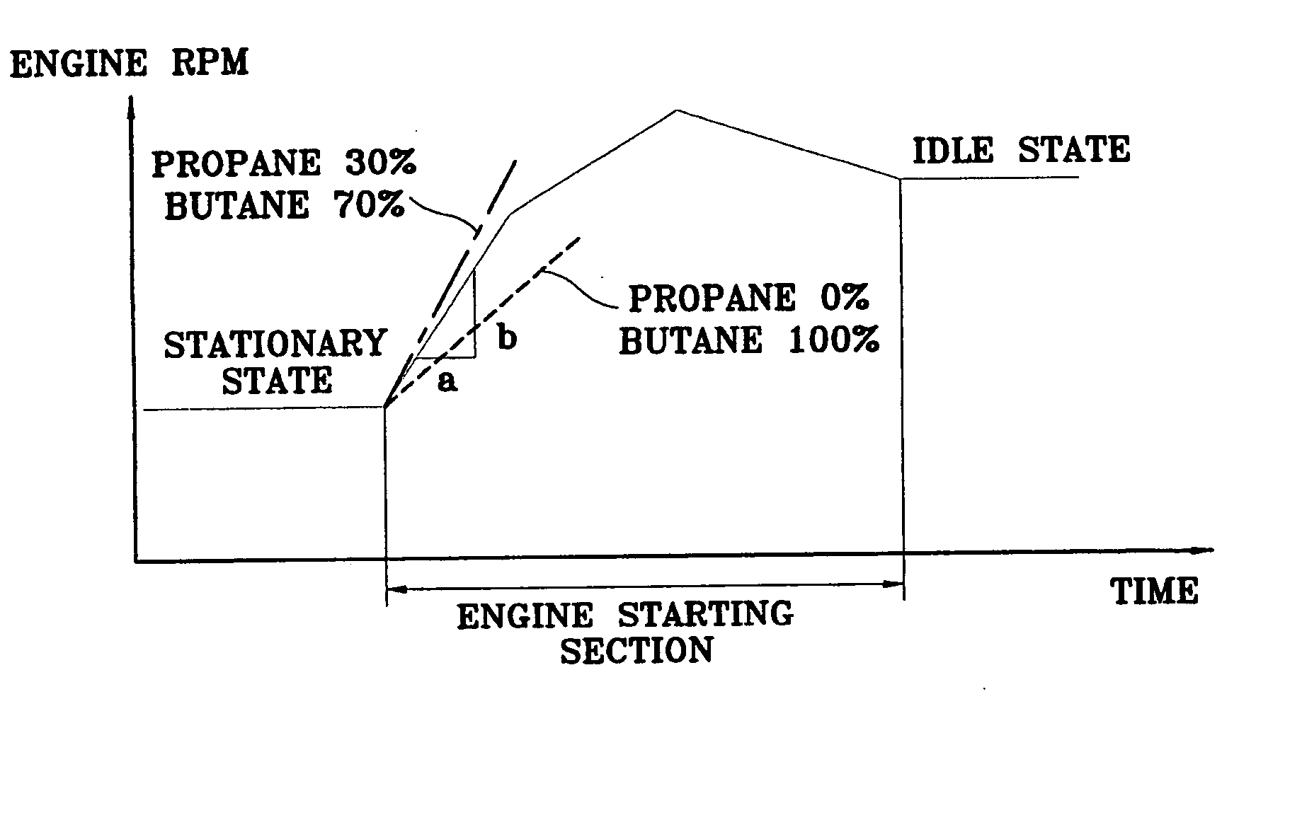
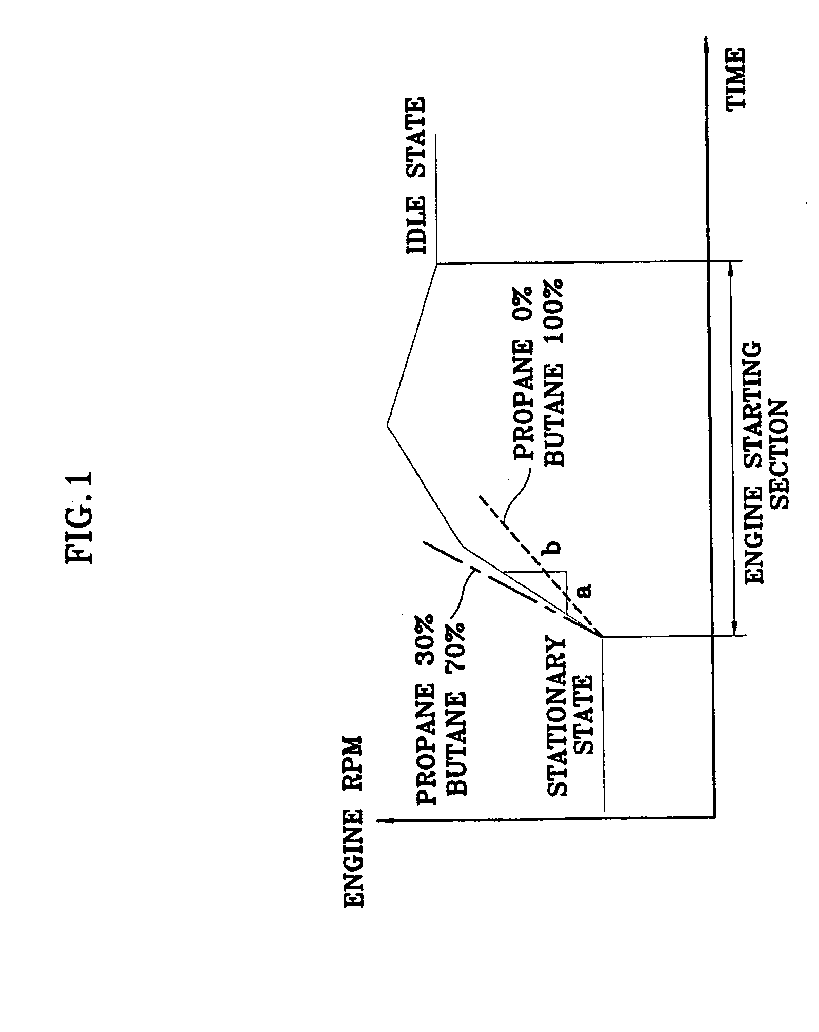
[0021] As discussed, the invention provides methods and systems for fuel injection control and effective use of a Liquefied Petroleum gas Injection (LPI) engine. Preferred methods and systems may suitably comprise determining engine revolution per unit time (such as revolution per minute (rpm)) and fuel temperature after the start of an engine; determining fuel pressure by consideration of the determined amount of the engine revolution per revolution per unit time and fuel temperature; determining the propane content of liquefied petroleum gas of the engine by consideration of the fuel temperature and fuel pressure; and controlling one or more fuel injection properties by using a map prepared with consideration of the fuel propane content. Fuel injection properties that are controlled may suitably include fuel injection time and / or fuel injection period. Preferred methods and systems may further comprise detecting if the engine has been started, and after detecting an engine start, ...


PUM


Abstract

Fuel injection control methods and systems and related apparatus for Liquefied Petroleum gas Injection (LPI) engine are provided. Preferred methods and systems determine the increased amount of engine revolution per unit time and fuel temperature during an initial engine start period; determine fuel pressure on the basis of such values; determines propane content of the engine fuel by consideration of the fuel pressure and fuel temperature of the P-T diagram of the fuel; and controls the fuel injection time and injection period by using a map prepared according to propane content. Preferred systems and methods of the invention need not include use of fuel pressure and temperature sensors that provide injection control conditions to an Engine Control Unit, thereby providing a simplified and more efficient apparatus.

Description

CROSS-REFERENCE TO RELATED APPLICATIONS [0001] The present application is based on, and claims priority from, Korean Application Serial Number 10-2003-0075058, filed on Oct. 27, 2003, the disclosure of which is hereby incorporated by reference herein in its entirety. FIELD OF THE INVENTION [0002] The present invention relates to fuel injection control methods and systems for a Liquefied Petroleum Gas Injection (LPI) engine. More particularly, in a preferred aspect, the present invention is adapted to compute propane content contained in Liquefied Petroleum Gas (LPG) when a vehicle is initially started and to control fuel injection according to the computed value. BACKGROUND OF THE INVENTION [0003] In general, LPG fuel stored in a vehicle engine LPG tank (which is also called a bombe) is vaporized in the vaporizer and then blended with exterior air in the mixer for supply into the engine cylinder. However, in the case of an LPI engine using LPG as fuel, the fuel is directly injected ...

Claims


Application Information

Patent Timeline
Patent Type & Authority Applications(United States)
IPC IPC(8): F02D19/02F02D41/00F02M21/02F02D41/02F02D41/06F02D41/20F02D41/34F02D45/00
CPCF02D41/0027F02D41/062F02D2200/0611Y02T10/32F02D19/028F02D19/024F02D19/025F02D19/029F02M21/0212Y02T10/30F02M21/02
Inventor KANG, DAE-JIN
Owner HYUNDAI MOTOR CO LTD
Features
  • R&D
  • Intellectual Property
  • Life Sciences
  • Materials
  • Tech Scout
  • Unparalleled Data Quality
  • Higher Quality Content
  • 60% Fewer Hallucinations
Learn More