
Cable handling system

a handling system and cable technology, applied in the direction of hoisting equipment, load-engaging elements, waterborne vessels, etc., can solve the problems of equipment sinking into muddy and sandy sea beds, affecting the operation of equipment, and affecting the safety of equipment, so as to dampen the stress on the cable and reduce the force on the cable

Inactive Publication Date: 2005-04-28
PGS ONSHORE INC
View PDF10 Cites 35 Cited by
  • Summary
  • Abstract
  • Description
  • Claims
  • Application Information

AI Technical Summary

Benefits of technology

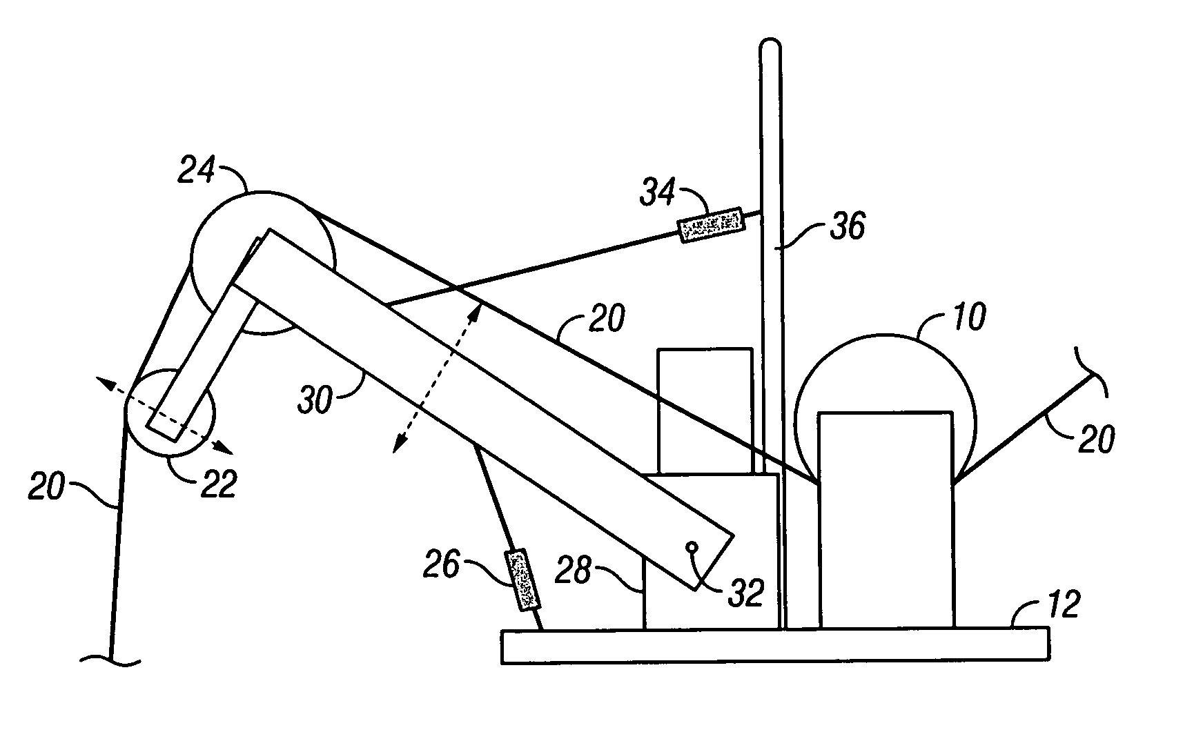
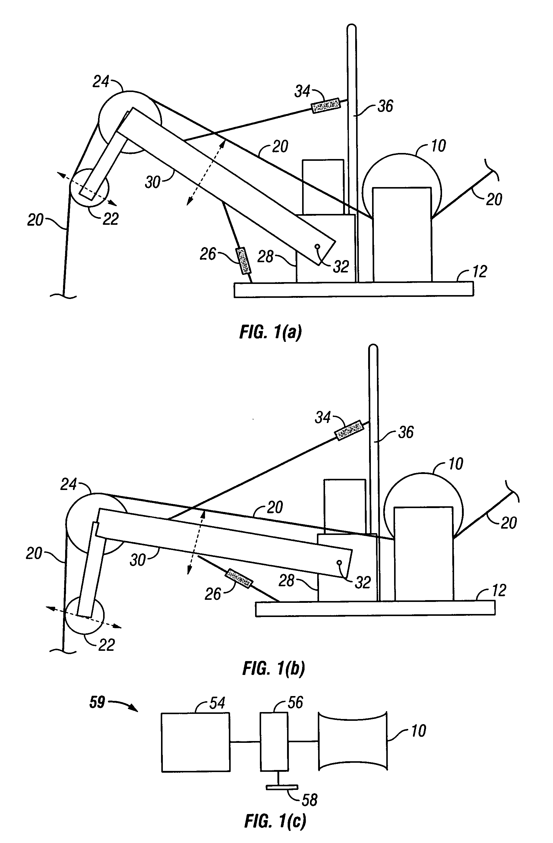
[0010] A preferred embodiment comprises a pulling drum capable of pulling the cable by wrapping the cable around the drum, thereby distributing pulling forces across the components of the cable. The pulling drum may be powered by a drive motor with a regulatable torque drive for adjusting the forces on the cable. Alternatively, the drum may be powered by a clutching system or by a hydraulic torque conversion system set to slip or stall at a selectable force value. Any means for powering the drum may preferably allow payback of the cable to lessen forces on the cable if needed to avoid damage to the cable. Preferably the apparatus or system will also have a front-mounted damper arm with an adjustable tension range positioned in front of the pulling drum to dampen stress on the cable, particularly stress caused by the movement of the water.

Problems solved by technology

However, precisely deploying and later retrieving such equipment without damaging the equipment can be difficult.
Operations in water, especially oceans, bays, and surf zones, can be especially problematic.
The equipment commonly sinks into muddy and sandy sea beds and tends to suffer stress damage when removed.
Seismic cables can be especially difficult to handle because they are typically made of multiple components such as electrical conductors, fiber optics, and stress supporting members all bundled together and covered with a protective jacketing material.
Handling or pulling the cable causes these components to slip and move with respect to one another.
Propagation of stress through a cable's components changes and deteriorates the components and consequently reduces the cable's useful life.
Pulling cable up from a sea bottom and through sea bottom material is stressful to equipment in the cable, but simply pulling the cable through water is also stressful.
The curve of the cable inevitably causes portions of the cable to be pulled sideways through the water, creating vortexes in the water, cable strumming, and drag on the cable, and adding further to the stresses on the cable.
Such pulling tensions can exceed the strength of the cable, causing it to break.
Similarly, tensions caused by pulling of the cable due to heaving of the vessel on ocean waves and swells can exceed the strength of the cable, causing it to suffer elongation damage and even break.

Method used


Image

  • Cable handling system
  • Cable handling system
  • Cable handling system

Examples


Embodiment Construction

[0020] According to the invention, a pulling device is provided that allows cable to be retrieved from water and sea beds without damage or fouling from the pulling process to either the cable components or attachments to the cable, even though such attachments may be wider than the cable itself. Cable components may include, for example, internal stress members, protective jackets, electrical and fiber optic conductors and insulating layers. Attachments to the cable may include, for example, sensor packages and other electrical or fiber optic equipment.

[0021] The pulling device distributes pulling forces and stresses among preferably all of the cable components, most preferably substantially equally among all of the cable components, including internal stress members of the cable and external jacketing material.

[0022] In a preferred embodiment, referring to FIGS. 1(a) and 1(b), the pulling device comprises a pulling drum 10, rotatably mounted on a preferably firm, stationary or r...


PUM


Abstract

A system or apparatus and method for retrieving cable from water during marine operations is provided that reduces damage to the cable from pulling forces during the retrieval. A pulling device distributes the forces and stresses all along the cable components. In one embodiment, the pulling drive comprises a pulling drum powered by a clutching system or by a hydraulic torque conversion system set to slip or stall at a selectable force value. The apparatus may use a see-saw action to maintain the forces below damaging levels. The system may be adapted for deploying cable in marine operations as well.

Description

BACKGROUND OF THE INVENTION [0001] 1. Field of the Invention [0002] The present invention relates to cable handling systems, particularly systems for deploying and retrieving electrical and fiber optic cables. Most particularly, the invention relates to marine seismic cable deployment and retrieval systems for use in conjunction with a marine vessel. [0003] 2. Brief Description of Relevant Art [0004] In many fields of endeavor, there is an on-going requirement to place packages of sensing equipment of various types across the earth's surface and on the seafloor. Such equipment is commonly intended to be used at one location for a period of time and then transported to a different location for further use. However, precisely deploying and later retrieving such equipment without damaging the equipment can be difficult. Operations in water, especially oceans, bays, and surf zones, can be especially problematic. The equipment commonly sinks into muddy and sandy sea beds and tends to suf...

Claims


Application Information

Patent Timeline
Patent Type & Authority Applications(United States)
IPC IPC(8): B66C13/02B66D1/52
CPCB66D1/52B66C13/02
Inventor SCOTT, GARY LEE
Owner PGS ONSHORE INC
Learn More