Organic polarized light emitting diode display with polarizer

a light-emitting diode and organic technology, applied in the direction of discharge tube luminescnet screen, discharge tube/lamp details, organic semiconductor devices, etc., can solve the problems of reducing the reflectance of ambient light from the surface, emitted light may be lost to 90 %, etc., and achieves higher contrast and higher efficiency

Inactive Publication Date: 2005-04-28
EASTMAN KODAK CO
View PDF21 Cites 73 Cited by
  • Summary
  • Abstract
  • Description
  • Claims
  • Application Information

AI Technical Summary

Problems solved by technology

Thus in an OLED display with a polarizer, over 90% of the emitted light may be lost.
Using this technique, it is theoretically possible to outcouple up to 93% of the light emitted by the organic luminescent materials in an organic luminescent device, however this technique does not reduce the reflectance of ambient light from the surface of the display.

Method used


Image

  • Organic polarized light emitting diode display with polarizer
  • Organic polarized light emitting diode display with polarizer
  • Organic polarized light emitting diode display with polarizer

Examples


Embodiment Construction

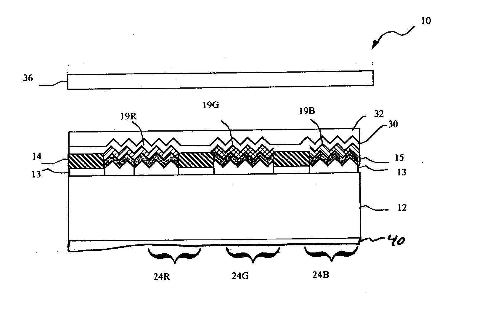
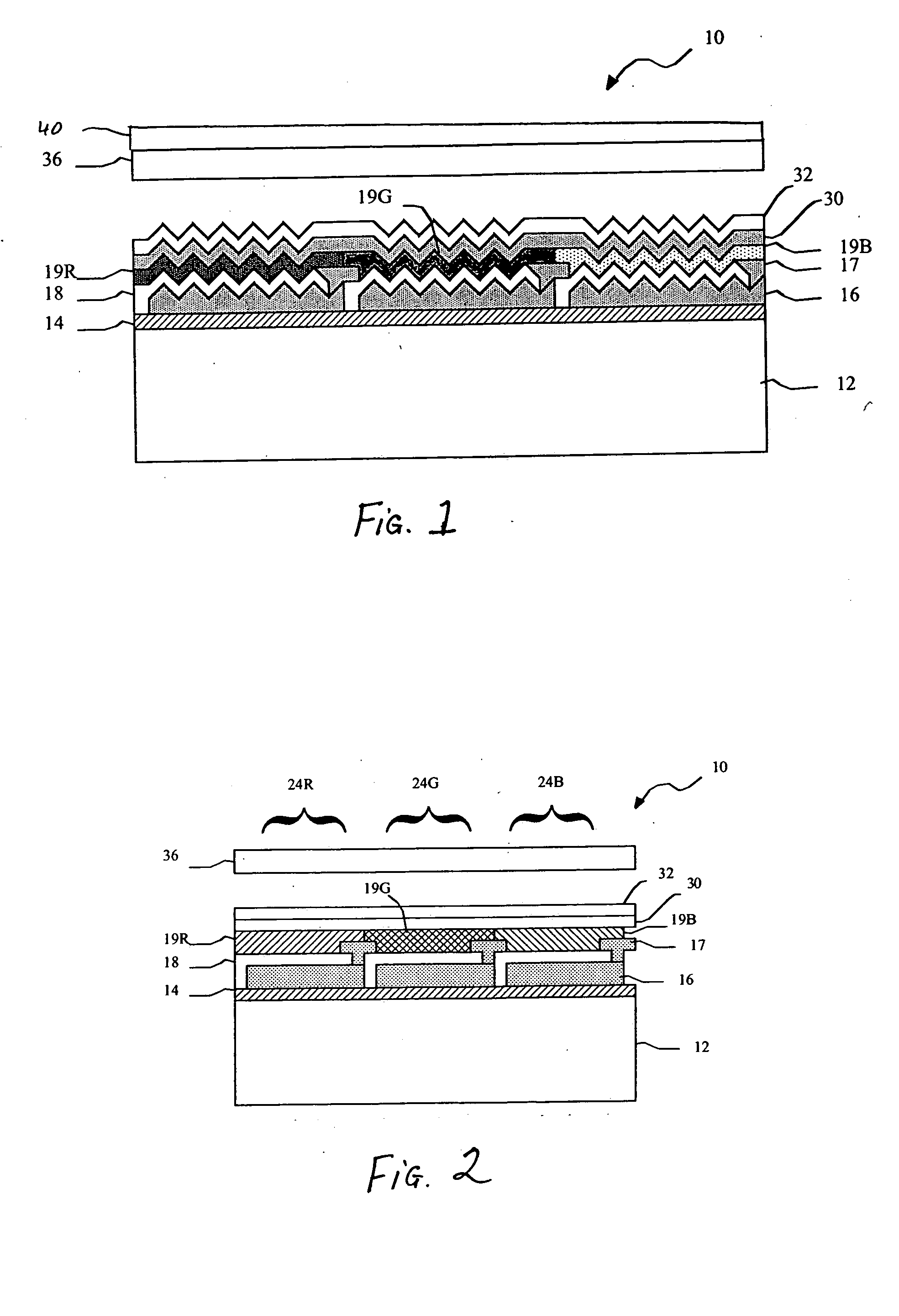
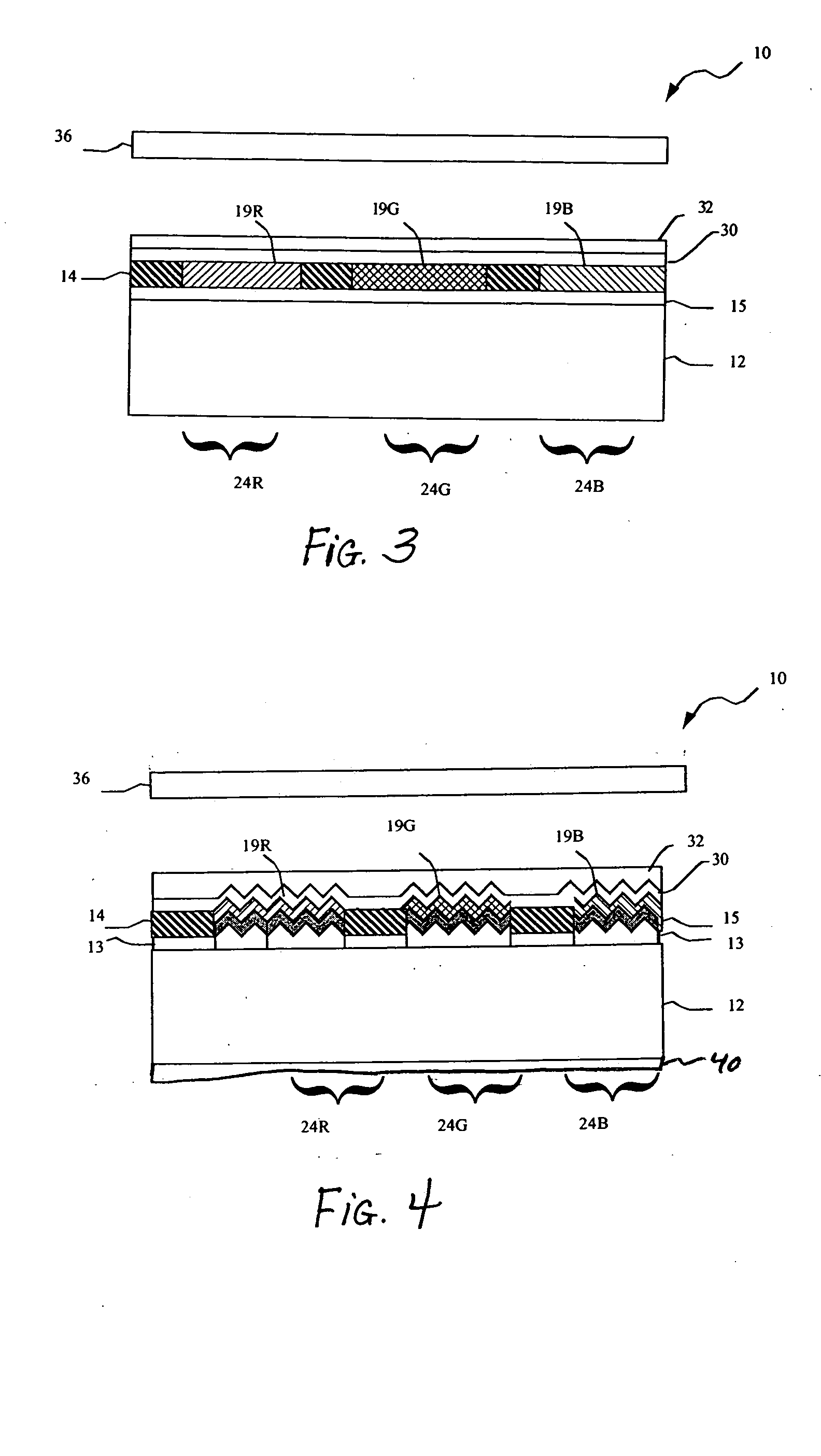
[0012] Referring to FIG. 2, a prior art top emitting OLED display device 10 includes a substrate 12, and a thin film transistor (TFT) active matrix layer 14 comprising an array of TFTs that provides power to OLED elements. A patterned and planarized first insulating layer 16 is provided over the TFT active matrix layer, and an array of first electrodes 18 are provided over the planarized insulating layer 16 and in electrical contact with the TFT active matrix layer. A patterned second insulating layer 17 is provided over the array of first electrodes 18 such that at least a portion of the each of the first electrodes 18 is exposed.

[0013] Over the first electrodes and insulating layers are provided red, green, and blue-emitting organic OLED elements, 19R, 19G, and 19B, respectively. These elements are composed of further layers as described in more detail below. Herein, the collection of OLED elements, including hole injection, hole transport, and electron transport layers may also ...


PUM


Abstract

An organic light emitting diode display includes a substrate; a plurality of OLEDs formed on the substrate, the OLEDs emitting polarized light wherein the OLEDs comprise a layer defining a periodic grating structure; a first electrode layer conforming to the grating structure; an OLED material layer formed over the first electrode layer and conforming to the grating structure; and a second electrode layer formed over the OLED material layer and conforming to the grating structure, wherein the first and / or second electrode layers are metallic layers, whereby the periodic grating structure induces surface plasmon cross coupling in the metallic electrode layer(s) to emit polarized light; and a polarizer located over the substrate through which the polarized light is emitted.

Description

FIELD OF THE INVENTION [0001] The present invention relates to organic light emitting diode displays, and more particularly to increasing the light output from the emissive layers. BACKGROUND OF THE INVENTION [0002] It is known to use polarizers with flat panel displays such as LCD and OLED displays to reduce the reflection of ambient light on the front of the flat panel displays. Circular polarizers are known to improve contrast in light emitting displays, for example, as disclosed in U.S. Pat. No. 4,100,455 issued Jul. 11, 1978 to DuBois; JP 03-222287; and U.S. Pat. No. 6,549,335 B1 issued Apr. 15, 2003 to Trapani et al. U.S. Pat. No. 6,392,727 B1 issued May 21, 2002 to Larson et al. describes the use of circular polarizers with LCD flat-panel displays. [0003] However, in an OLED display, circular polarizers while absorbing more than 99% of the ambient light incident on the polarizer, also absorb up to 60% of the light emitted from the OLED display. Moreover, much of the light out...

Claims


Application Information

Patent Timeline
Patent Type & Authority Applications(United States)
IPC IPC(8): H01L27/32H01L51/52
CPCH01L27/3211H01L27/3244H01L27/3281H01L2251/5315H01L51/5281H01L51/5293H01L51/5262H10K59/35H10K59/12H10K59/17H10K50/85H10K50/86H10K50/868H10K2102/3026
Inventor COK, RONALD S.
Owner EASTMAN KODAK CO
Why Eureka
Try Eureka