Gas-discharge tube and display apparatus
a technology of gas discharge tube and display apparatus, which is applied in the direction of gas discharge electrodes, gas-filled discharge tubes, multiple discharge path lamps, etc., can solve the problems of display defect, non-uniform surface tension applied to coated liquid, and the same situation as described above, so as to eliminate the dispersion of the position and stable discharge characteristics
- Summary
- Abstract
- Description
- Claims
- Application Information
AI Technical Summary
Benefits of technology
Problems solved by technology
Method used
Image
Examples
embodiment 1
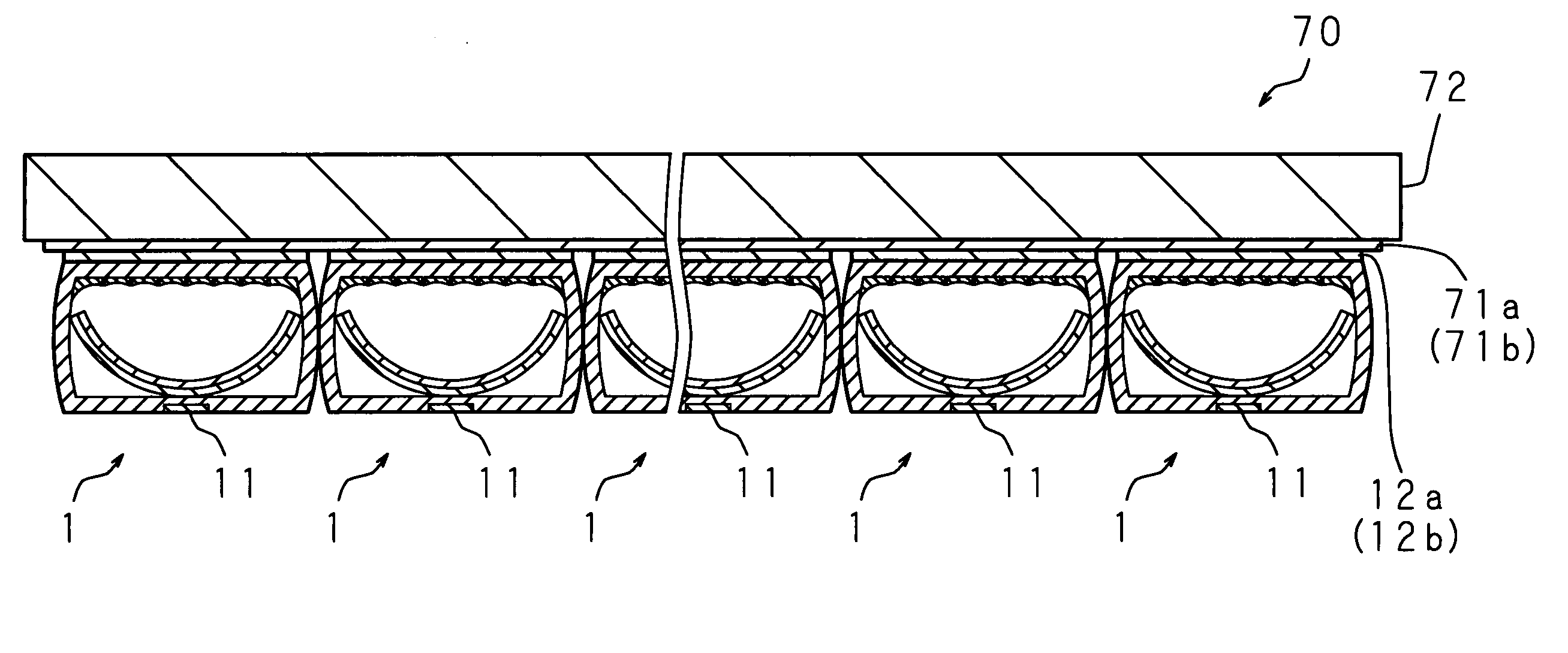
[0051]FIG. 3 is a schematic perspective view showing the outlook of a gas-discharge tube according to Embodiment 1 of the present invention and FIG. 4 is a schematic cross sectional view showing the structure along line II-II of FIG. 3. A gas-discharge tube 1 according to the present Embodiment 1 uses a glass tube 10 made from light transmissible glass (for example, borosilicate glass) as a tubular body whose inner periphery and outer periphery of the cross section across the axis are both approximately rectangular. A trench 10a is provided in an axial direction of the glass tube 10 on the outside of one side (the side-facing the discharge surface) within glass tube 10, and an address electrode 11 is placed in this trench 10a. On the other hand, a plurality of sustain electrodes 12a and 12b is placed at predetermined intervals parallel to the direction crossing the axial direction of the glass tube 10 on the external surface of the side that faces the side of glass tube 10 where the...
embodiment 2
[0065]FIG. 9 is a schematic cross sectional view showing the structure of a gas-discharge tube according to Embodiment 2 of the present invention. A gas-discharge tube 3 according to Embodiment 2 is made from a glass tube 30 as a main body where the inner periphery and the outer periphery of the cross section across the axis are both rectangular shape. A trench 30a is provided in the axial direction of the glass tube 30 on one surface (the surface facing the discharge surface) among the external surfaces of the glass tube 30. The thickness of the glass tube 30 is approximately constant, and the inside of the glass tube 30 of a portion where the trench 30a is provided on the external surface has a shape protruding toward the inside. An address electrode 11 is placed in the trench 30a. Sustain electrodes 12a and 12b are placed at a predetermined interval parallel to the direction crossing the axial direction of the glass tube 30 on the external surface of the glass tube 30 of the side...
embodiment 3
[0068]FIG. 10 is a schematic cross sectional view showing the structure of a gas-discharge tube according to Embodiment 3. The gas-discharge tube 4 according to Embodiment 3 is made from a glass tube 40 as a main material whose inner periphery of the cross section across the axis is circular shape, and the outer periphery of the cross section across the axis is approximately rectangular shape. An address electrode 11 is placed in the axial direction of the glass tube 40 on an external surface of the glass tube 40. Sustain electrodes 12a and 12b are placed at a predetermined distance parallel to the direction crossing the axial direction on the external surface of the glass tube 40, opposed to the address electrode 11. The address electrode 11 and the sustain electrodes 12a and 12b are placed so as to cross each other in the plan view, and each region defined by the intersection between the address electrode 11 and the sustain electrodes 12a and 12b becomes a unit emitting region (ce...
PUM
 Abstract
Description
Claims
Application Information
 - R&D
- Intellectual Property
- Life Sciences
- Materials
- Tech Scout
- Unparalleled Data Quality
- Higher Quality Content
- 60% Fewer Hallucinations
Browse by: Latest US Patents, China's latest patents, Technical Efficacy Thesaurus, Application Domain, Technology Topic, Popular Technical Reports.
© 2025 PatSnap. All rights reserved.Legal|Privacy policy|Modern Slavery Act Transparency Statement|Sitemap|About US| Contact US: help@patsnap.com


