Two-legged walding locomotion apparatus and its walking controller

a locomotion apparatus and controller technology, applied in manipulators, instruments, computing, etc., can solve the problems of inability to accurately conduct zmp compensation, robots may fall down with collapsed walking posture, and the inability to walk with bifocals

Inactive Publication Date: 2005-04-28
JAPAN SCI & TECH CORP
View PDF8 Cites 10 Cited by
  • Summary
  • Abstract
  • Description
  • Claims
  • Application Information

AI Technical Summary

Benefits of technology

[0007] It is the object of the present invention, taking into consideration the above-mentioned problems, to provide a biped walking mobile system and its walk control system to realize walk stability by accurately detecting floor reaction force at a sole in the unstable road condition with complex roughness.
[0017] According to said aspect, a drive means is drive-controlled by modifying by a compensator the gait data from a gait former based on the force detected by a force detector comprising at least three 3-axial force sensor allocated on a sole of each foot portion. In that case, when a foot portion lands on the road surface with complex roughness, the three 3-axial force sensors protruding downward from a sole steadily contact the road surface. Therefore, the stabilization of a main body, for example, a humanoid robot's upper body can be maintained by accurately modifying the gait data based on the detected signal from three 3-axial force sensors which detect effective force even on unstable road surface. Accordingly, even on unstable road surface with complex roughness, a sole of each foot portion of a robot can maintain the stability of a robot, and make possible steady walk control.
[0018] In case that three 3-axial force sensors are allocated at three tops of an isosceles triangle on a sole of respective foot portion, two of the 3-axial force sensors at the both ends of the bottom side of an isosceles triangle are in symmetrical condition, therefore the weight loaded on each 3-axial force sensor can be distributed evenly on left and right, and each 3-axial force sensor can be easily calibrated.
[0019] In case that each 3-axial force sensor is allocated on a periphery of a circle with the center on the vertical drive axis of a foot portion on a sole of respective foot portion, the torques around said vertical drive axis are in the same condition, therefore the loads with respect to said torques can be evenly distributed to each 3-axial force sensor, and each 3-axial force sensor can be easily calibrated with respect to the torques.
[0021] In case that one of the 3-axial force sensors is allocated near an base portion, and another 3-axial force sensor is allocated near the tip of a toe portion, and still two other 3-axial force sensors are allocated left and right in the region near the border of an base portion and a toe portion, when only an base portion or a toe portion is in contact with the ground, three 3-axial force sensors of a force detector are in contact with the ground, and can accurately detect the floor reaction force on a sole.

Problems solved by technology

However, such a biped walking robot tends to be unstable in walking posture upon walking due, for example, to road surface conditions, or the error of the robot's own physical parameters, or else, and may tumble down in some cases.
On the other hand, if a robot is made to conduct walk control without pre-designed gait data while confirming walk conditions in real time, then walking is possible with stable walking posture, but even in such cases, the robot may tumble down with collapsed walking posture, when unexpected road conditions are encountered.
However, as for a biped walking robot of such structure, there may be such cases where a whole sole does not land on the road surface in the unstable road condition with complex roughness, and floor reaction force at a sole can not be accurately detected, and thereby ZMP compensation can not be accurately conducted.
For this reason, the robot's stability can not be maintained, and the robot's biped walking becomes difficult.

Method used


Image

  • Two-legged walding locomotion apparatus and its walking controller
  • Two-legged walding locomotion apparatus and its walking controller
  • Two-legged walding locomotion apparatus and its walking controller

Examples


Embodiment Construction

[0035] Hereinafter, the present invention will be described in detail with reference to suitable forms of embodiment thereof illustrated in the figures.

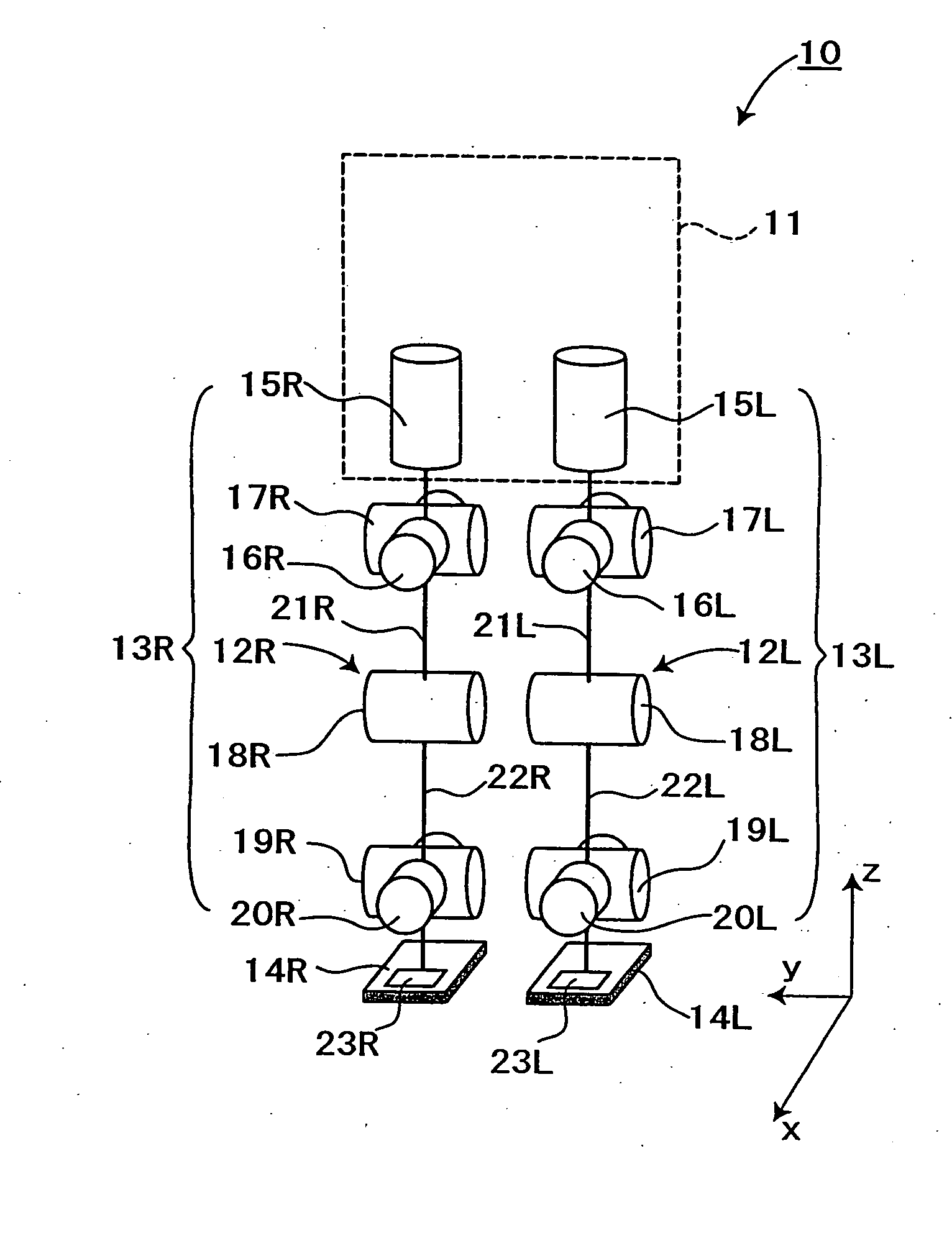
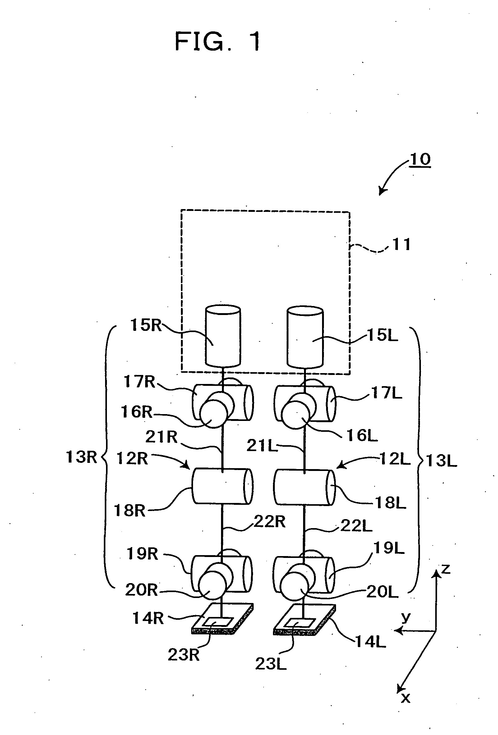
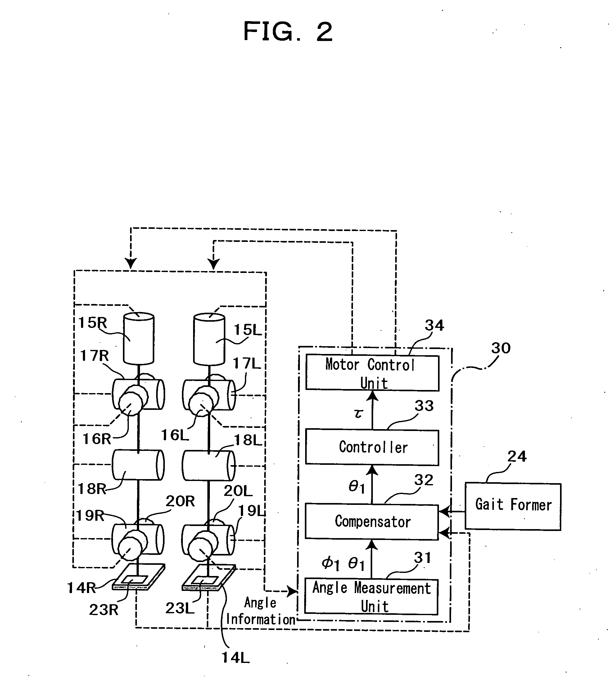
[0036]FIG. 1 and FIG. 2 show the makeup of an embodiment of a biped walking robot with a biped walking mobile system applied thereto in accordance with the present invention. Referring to FIG. 1, a biped walking robot 10 includes an upper body 11 as a main body having at both sides of its lower part a pair of leg portions 13L and 13R attached thereto, each of the leg portions having a knee portion 12L, 12R in its midway, and a foot portion 14L, 14R at its lower end.

[0037] Here, each of said leg portions 13L, 13R has six joint portions, namely in the order from above, the joint portion 15L, 15R for the leg portion rotation of a waist (around z axis) with respect to the upper body 11, the joint portion 16L, 16R for the roll direction of a waist (around x axis), the joint portion 17L, 17R for the pitch direction of a waist (around y a...


PUM


Abstract

A walk controller (30) for a biped (two-footed) walking mobile system, which drive-controls each joint drive motor (15L, 15R-20L, 20R) of each leg portion (13L, 13R) of a biped walking mobile system based on gait data, includes a force detector (23L, 23R) to detect the force allied to a sole of each foot portion (14L, 14R), and a compensator (32) to modify the gait data from a gait former (24) based on the force detected by a force detector, and is constituted so that each force detector (23L, 23R) comprises at least three 3-axial force sensors (36a, 36b, 36c) allocated on a sole of each foot portion (14L, 14R), and a compensator (32) modifies gait data based on the detected signals from three 3-axial force sensors (36a, 36b, 36c) which detect effective force, thereby the walk stability of a robot is realized, even on the unstable road surface condition with complex roughness.

Description

TECHNICAL FIELD [0001] The present invention relates to a biped (two-footed) walking mobile system, and more specifically to its walk control system which leads to stable walking. BACKGROUND ART [0002] A conventional biped walking robot generates the pre-designed walk pattern (hereinafter to be called “gait”) data, conducts walk control according to said gait data, moves foot portions by the predetermined walk pattern, and thereby realizes biped walking. [0003] However, such a biped walking robot tends to be unstable in walking posture upon walking due, for example, to road surface conditions, or the error of the robot's own physical parameters, or else, and may tumble down in some cases. On the other hand, if a robot is made to conduct walk control without pre-designed gait data while confirming walk conditions in real time, then walking is possible with stable walking posture, but even in such cases, the robot may tumble down with collapsed walking posture, when unexpected road co...

Claims


Application Information

Patent Timeline
Patent Type & Authority Applications(United States)
IPC IPC(8): B25J5/00B25J13/08B62D57/02B62D57/032
CPCB25J13/085B62D57/032B62D57/02B25J5/00B25J13/08
Inventor FURUTA, TAKAYUKITAWARA, TETSUOOKUMURA, YUKITANO, HIROAKI
Owner JAPAN SCI & TECH CORP
Why Eureka
Try Eureka