Scanning exposure technique

a scanning exposure and exposure technique technology, applied in the field of scanning exposure technique, can solve the problems of difficult to eliminate tracking deviations, difficult to eliminate wafer cost and process management, etc., and achieve the effect of improving focus tracking performan

Inactive Publication Date: 2005-04-28
CANON KK
View PDF14 Cites 27 Cited by
  • Summary
  • Abstract
  • Description
  • Claims
  • Application Information

AI Technical Summary

Benefits of technology

[0012] The present invention has as its exemplified object t...

Problems solved by technology

This forces disadvantageous conditions in term of the wafer cost and process management.
However, in a scanning exposure apparatus, it is difficult to eliminate a tracking deviation with respect t...

Method used


Image

  • Scanning exposure technique
  • Scanning exposure technique
  • Scanning exposure technique

Examples


Embodiment Construction

[0048] As the best mode for carrying out the present invention, an embodiment wherein a substrate serving as an object to be exposed is a semiconductor wafer will be described in detail below with reference to the drawings.

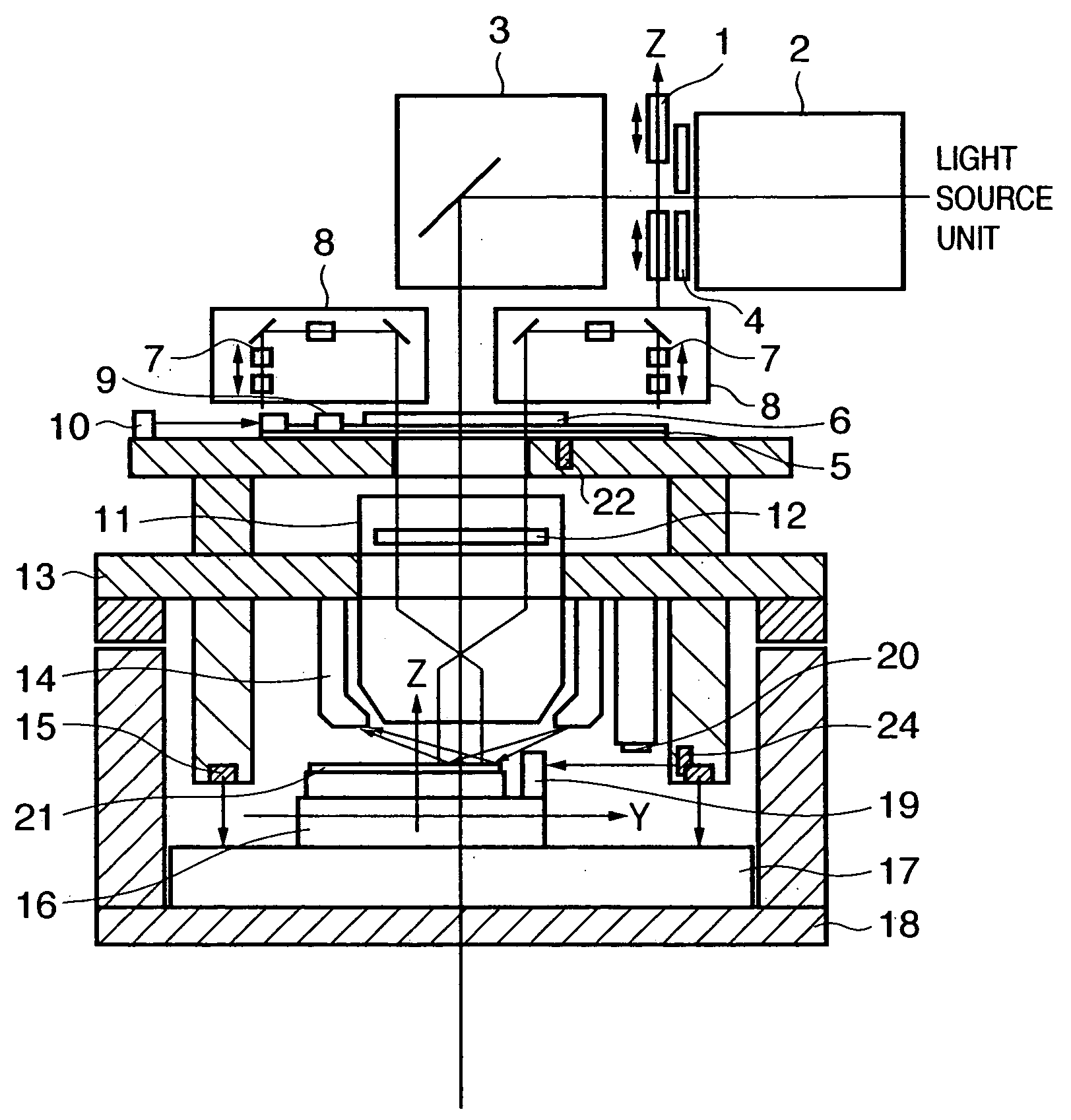
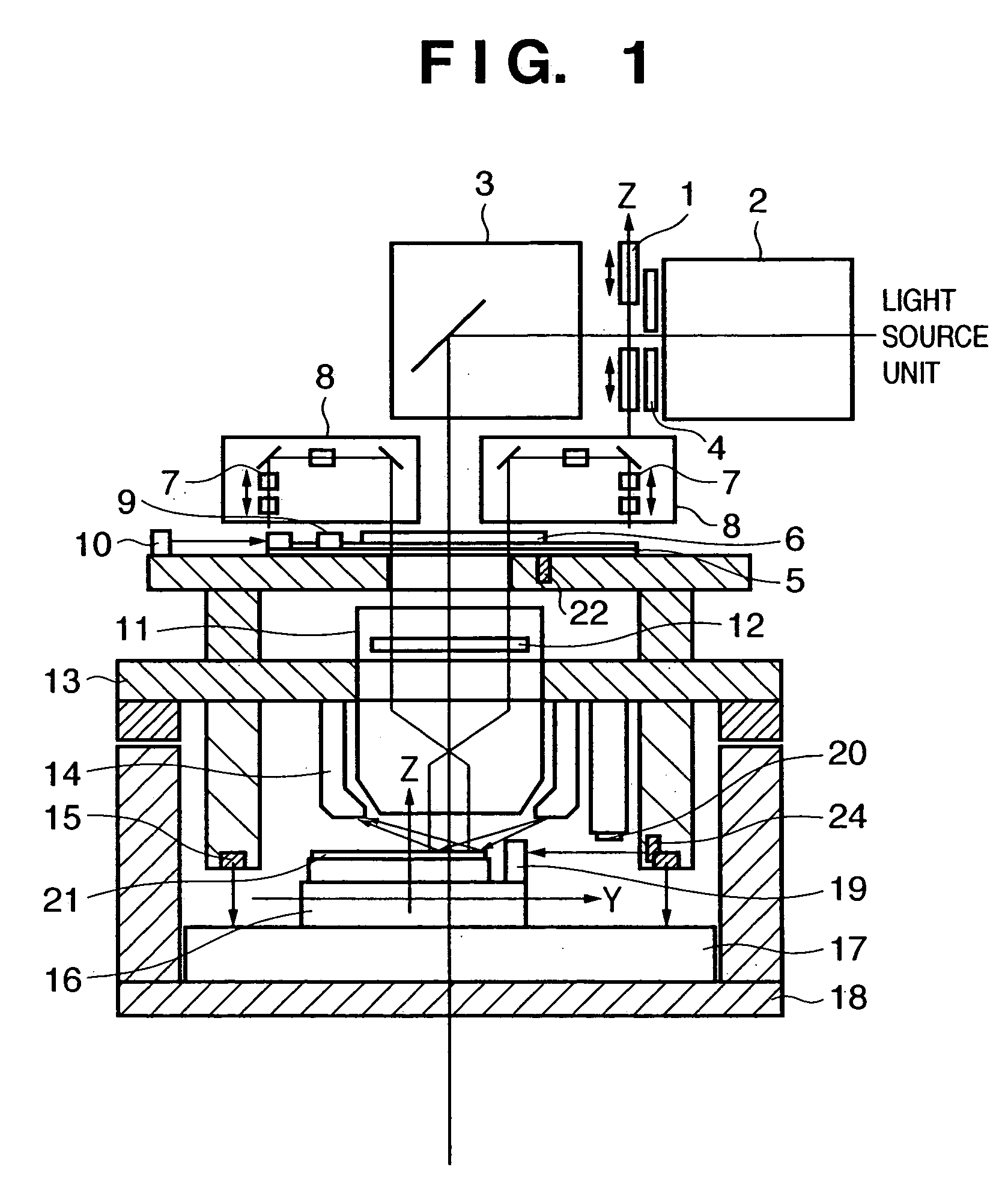
[0049]FIG. 1 is a view showing the schematic arrangement of a scanning exposure apparatus according to a preferred embodiment of the present invention. Exposure light from a light source unit such as an excimer laser reaches a slit 4 through a first condenser lens group 2. The slit 4 narrows a light beam of the exposure light to a slit-like beam having a dimension of about 7 mm in the Z direction and adjusts the illuminance integrated in the Z-axis direction so as to be uniform across a predetermined range in the X-axis direction. A masking blade 1 tracks the end of the pattern drawing field angle of a reticle (master) 6 in scanning exposure for a reticle stage (master stage) 5 and a wafer stage (substrate stage) 16. The masking blade 1 prevents exposure light fr...


PUM


Abstract

A scanning exposure apparatus includes an optical system which projects a pattern of an original onto a substrate, a stage which holds the substrate and moves in a scanning direction perpendicular to an optical axis of said optical system, a measurement system which measures a position, in a direction of the optical axis, of a surface region of the substrate, and a control system which performs feedback control of a position of said stage by generating data of a target position, in the direction of the optical axis, of said stage based on data of the position of the surface region measured by said measurement system, and performs feedforward control of the position of said stage by adding data of a surface shape of the substrate obtained in advance to the data of the target position, while moving said stage in the scanning direction.

Description

FIELD OF THE INVENTION [0001] The present invention relates to a scanning exposure technique. BACKGROUND OF THE INVENTION [0002] A process of measuring the surface position of a substrate such as a wafer while scanning the substrate to obtain a pattern offset (to be also referred to SPOC (Scanning Pattern Offset Compensation) hereinafter) will be described first. SPOC means scanning a plurality of shots on a process wafer and obtaining a three-dimensional pattern within each shot formed by wiring lines, insulators, and the like. A result obtained by averaging measurement data for the plurality of shots is used as pattern offset data for correcting an output from a focus measurement unit in scanning exposure. This allows smooth focusing (wafer movement) without tracking any slight step in a pattern within the shot. In a stationary exposure apparatus, generation of local defocus or offsets can be reduced by obtaining a shot representative plane free from the influence of any projectio...

Claims


Application Information

Patent Timeline
IPC IPC(8): G03F7/22G03F7/20G03F9/00G03F9/02H01L21/027
CPCG03F7/70725G03F9/7026G03F9/7003
Inventor KUROSAWA, HIROSHI
Owner CANON KK
Why Eureka
Try Eureka