Reflective display device

a display device and display technology, applied in the direction of optical elements, identification means, instruments, etc., can solve the problems of unintentional color mixture, abnormal display state, and inevitably created gap between beads, and achieve excellent display performan

Inactive Publication Date: 2005-04-28
SHARP KK
View PDF8 Cites 12 Cited by
  • Summary
  • Abstract
  • Description
  • Claims
  • Application Information

AI Technical Summary

Benefits of technology

[0024] In order to overcome the problems described above, preferred embodiments of the present inventio

Problems solved by technology

In that case, the display might exhibit an abnormal state.
For example, an incoming light ray that has passed a red color filter before reaching the retroreflector 8 may pass through a green or blue color filter on its way back, thus possibly causing a color mixture unintentionally.
In a reflector densely packed with beads on the other hand, a gap is created inevitably between the beads, no matter how densely those beads are packed, and such a gap never contributes to retroreflection.
As can be seen, in those reflectors obtained by densely packing beads or arranging triangular pyramidal concave portions, the percentage of the non-retroreflective portions to the overall reflector is too high to achieve sufficiently high retroreflectivity.
Actually, however, it is extremely difficult even to make a square corner cube reflector at such a small arrangement pitch (of 250 μm or less, for example).
Likewise, none of the other conventional methods of making square corner cubes mechanically such as a plate method and a pin bundling method is suitable to making a square corner cube reflector at that small arrangement pitch.
3466-3470, a square corner cube reflector can be formed at an even smaller arrangement pitch but it is still difficult to make a square corner cube reflector with a sufficiently high retroreflection property.
According to the non-mechanical methods mentioned above, it is difficult to make a square corner cube array in an almost ideal shape, and therefore, the actual retroreflection property deteriorates significantly from its theor

Method used


Image

  • Reflective display device
  • Reflective display device
  • Reflective display device

Examples


embodiment 1

[0095] Hereinafter, a reflective display device according to a first specific preferred embodiment of the present invention will be described.

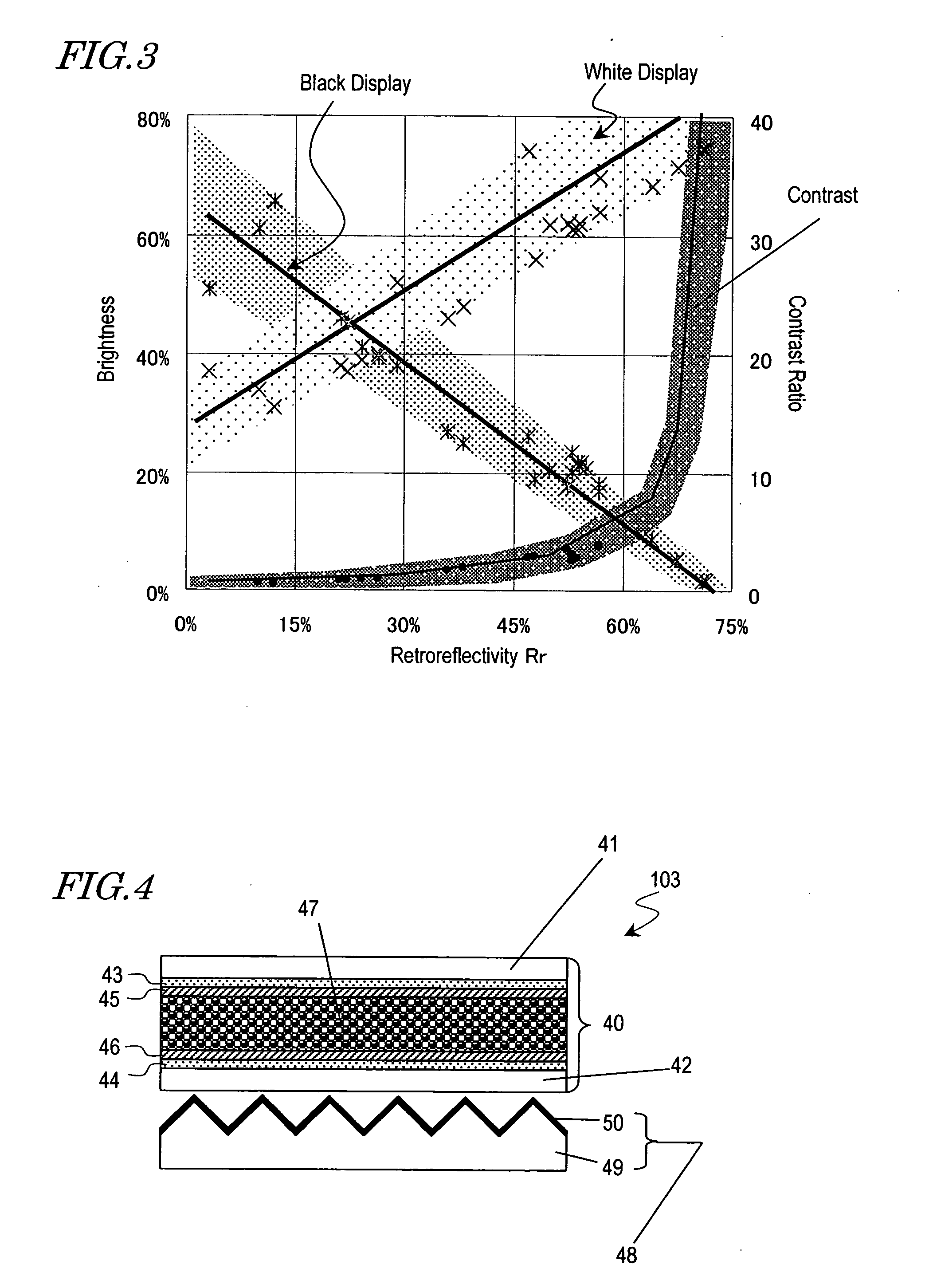
[0096] First, the configuration of a display device 103 according to this preferred embodiment will be described with reference to FIG. 4. The display device 103 includes a retroreflector 48 and a liquid crystal cell 40, which is provided closer to the viewer than the retroreflector 48 is.

[0097] The liquid crystal cell 40 includes a pair of transparent substrates 41 and 42 facing each other and a liquid crystal layer 47 interposed between the substrates 41 and 42. The transparent substrates 41 and 42 are made of a transparent material such as glass or a polymer film. On the surface of the transparent substrate 41 provided closer to the viewer, a transparent electrode 43 and an alignment film 45 are stacked in this order so as to face the liquid crystal layer 47. On the surface of the other transparent substrate 42, a transparent electrode 44...

embodiment 2

[0144] Hereinafter, a reflective display device according to a second specific preferred embodiment of the present invention will be described.

[0145] First, the configuration of a display device 104 according to this preferred embodiment will be described with reference to FIG. 10. The display device 104 of this preferred embodiment is preferably a color display device.

[0146] The display device 104 has the same configuration as the display device 103 of the first preferred embodiment described above except that the display device 104 further includes a color filter layer 51 between the transparent substrate 41 closer to the viewer and the transparent electrode 43. More specifically, the color filter layer 51 preferably includes red (R), green (G) and blue (B) color filters, which are arranged in a regular pattern, and an opaque layer (or black matrix (BM)) provided between adjacent color filters. Each of these color filters may have dimensions of 50 μm×150 μm, for example. It shou...

embodiment 3

[0150] Hereinafter, a reflective display device according to a third specific preferred embodiment of the present invention will be described.

[0151] First, the configuration of a display device 105 according to this preferred embodiment will be described with reference to FIGS. 11 and 12. The display device 105 of this preferred embodiment is an active-matrix-addressed display device.

[0152] As shown in FIG. 12, the display device 105 preferably includes a display section 91 and driver circuitry for driving the display section 91.

[0153]FIG. 11 shows a detailed configuration of the display section 91. As shown in FIG. 11, the display section 91 includes a liquid crystal layer 73 and a retroreflector 48, which are provided between a pair of substrates 71 and 72 that are opposed to each other. The substrate 71 is an active-matrix substrate including multiple thin-film transistors 76 thereon. The retroreflector 48 includes a square corner cube array 74, which is provided on the substr...


PUM


Abstract

A reflective display includes a retroreflective layer and a modulation layer, which is provided closer to a viewer than the retroreflective layer is and which is switchable between first and second states with mutually different optical characteristics. The retroreflective layer includes a two-dimensional arrangement of unit elements, which are arranged at a pitch of at most 250 μm. The retroreflective layer has a retro-reflectivity Rr of at least 45%. The retroreflectivity is defined as a ratio of the intensity of light, which has been reflected from the retroreflective layer and then received at a cone angle of 7.5 degrees by a retroreflectivity measuring system, to that of light, which has been reflected from a dielectric mirror and then received by the same retroreflectivity measuring system.

Description

BACKGROUND OF THE INVENTION [0001] 1. Field of the Invention [0002] The present invention relates to a reflective display device including a retroreflector and a method for evaluating the retroreflector. [0003] 2. Description of the Related Art [0004] Various configurations have been proposed for a reflective liquid crystal display device with a retroreflector (see Japanese Laid-Open Publication No. 2002-107519, Japanese Patent No. 3216584, and Japanese Laid-Open Publication No. 2002-287134, for example). Each of those reflective liquid crystal display devices uses no polarizers and therefore can conduct a display operation with increased brightness, and is also expected to achieve a display at a higher contrast ratio. As used herein, the “retroreflector” refers to an optical element that has a two-dimensional arrangement of very small unit elements so as to reflect any incoming light ray back to the source by way of multiple reflective surfaces thereof, no matter where the light ra...

Claims


Application Information

Patent Timeline
IPC IPC(8): G02B5/124G02F1/1335G09F9/00G09F13/16
CPCG02F1/133553G02B5/124G02F1/1335
Inventor FUJIWARA, SAYURIMINOURA, KIYOSHI
Owner SHARP KK
Why Eureka
Try Eureka