
Superwide-angle lens optical system, and imaging unit and display unit comprising the same

a wide-angle lens and optical system technology, applied in the field of super-wide-angle lens optical system, can solve the problems of long back focus with respect too large diameter of object-side lens, etc., and achieve the effect of easy arrangemen

Inactive Publication Date: 2005-04-28
OLYMPUS CORP
View PDF3 Cites 73 Cited by
  • Summary
  • Abstract
  • Description
  • Claims
  • Application Information

AI Technical Summary

Benefits of technology

[0015] The image-formation plane formed by the objective lens group is reformed through the relay optical system to make the back focus of the objective lens group short, thereby making the diameter of an object-side lens compact. Satisfaction of conditions (1-1) and (1-2), to which the lower limit is 1.8, makes it easy to ensure the back focus and the compact front lens diameter without recourse to the relay optical system.
[0063] As described above, the present invention typically provides a superwide-angle lens optical system that has a long back-focus lens arrangement and comprises a relay lens system which can be laid out with a high degree of flexibility and enables a plurality of optical systems to be efficiently laid out.

Problems solved by technology

However, when there is provided a back focus enough to receive an optical path-bending member such a quick return mirror used with single-lens reflect cameras, etc. and various filters, etc., a problem arises; the back focus becomes long with respect to the focal lengths of lenses, and so the diameter of an object-side lens becomes too large.
As the image circle of an image pickup plane increases, another problem arises; the diameter of the object-side lens becomes too large.
In addition, such prior art lens systems are not fit for improvements in the degree of flexibility in optical system layouts by incorporating a plurality of optical path-bending members, or layouts wherein a relatively wide air space is allowed for in a lens group to receive a plurality of optical systems efficiently.

Method used


Image

  • Superwide-angle lens optical system, and imaging unit and display unit comprising the same
  • Superwide-angle lens optical system, and imaging unit and display unit comprising the same
  • Superwide-angle lens optical system, and imaging unit and display unit comprising the same

Examples


Embodiment Construction

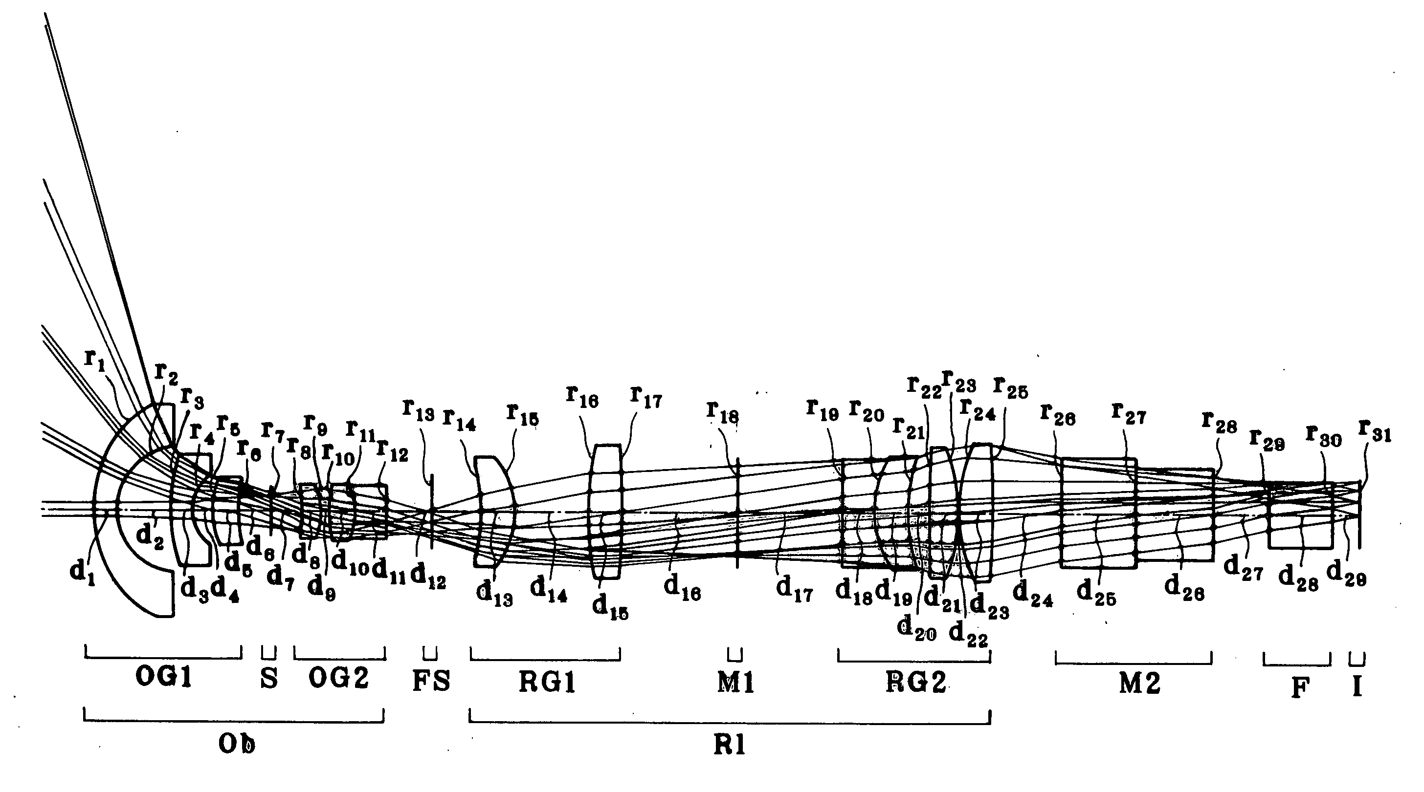
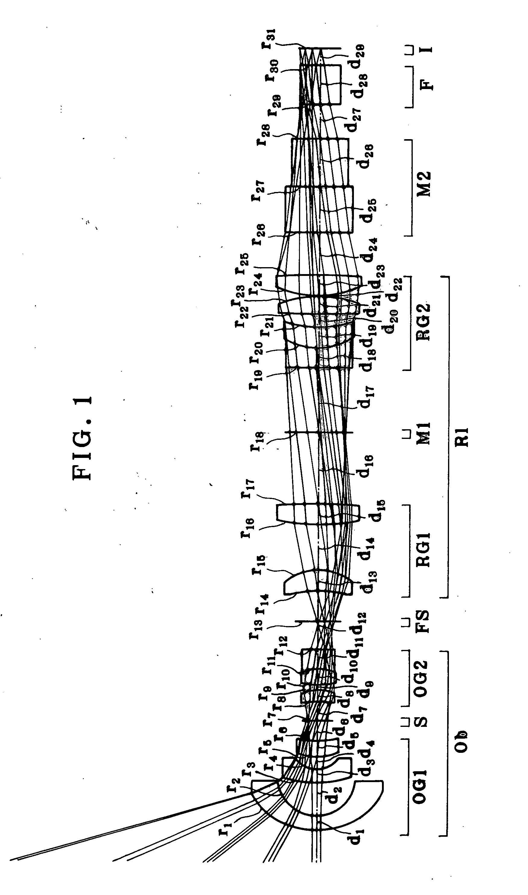
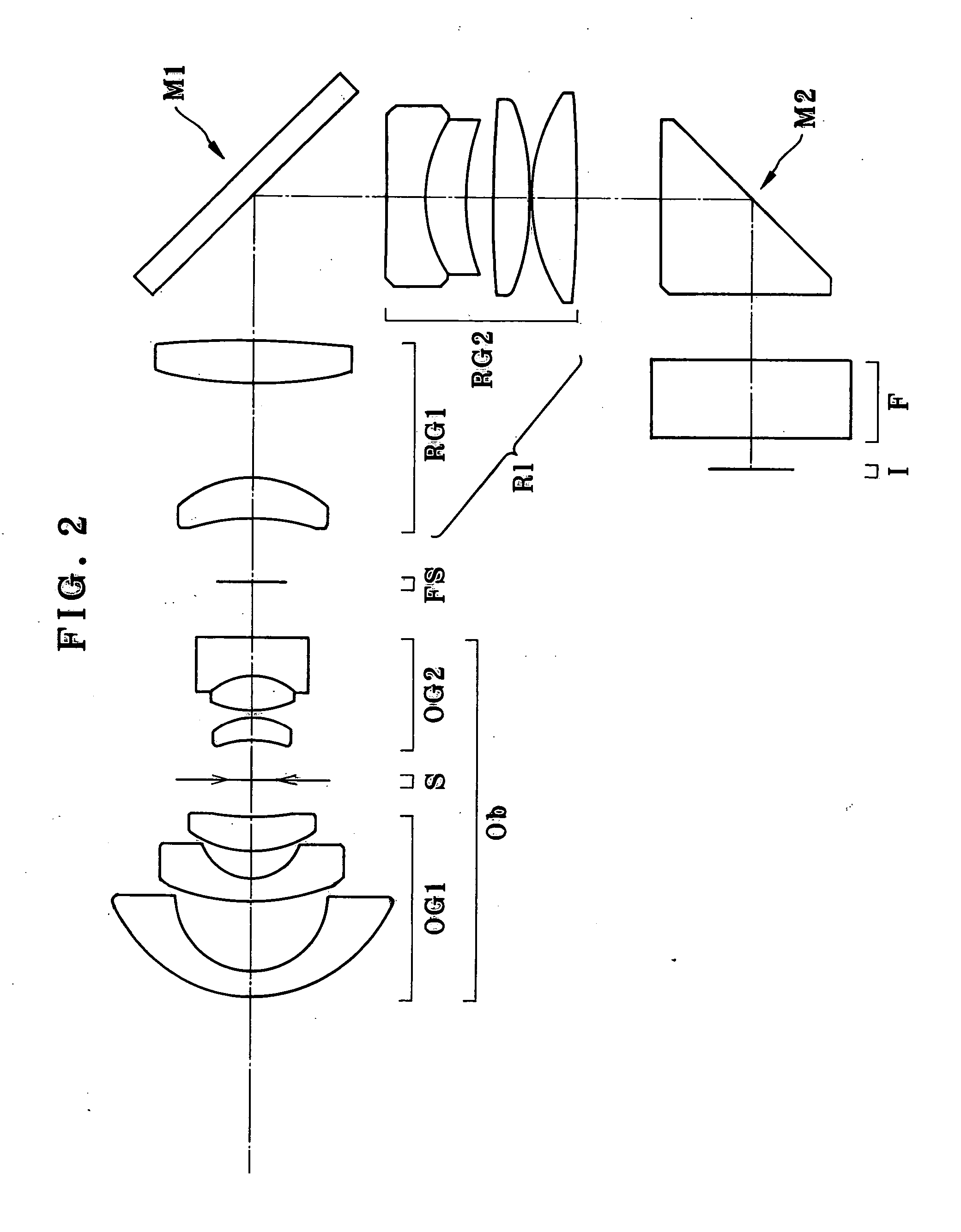
[0078] First of all, Example 1 of the superwide-angle lens optical system of the invention is now explained. FIG. 1 is a taken-apart optical path diagram for Example 1 upon focusing on an object point at infinity, and FIG. 2 is a sectional view as taken along the optical axis thereof.

[0079] As shown in FIGS. 1 and 2, Example 1 is directed to a superwide-angle lens optical system is composed of, in order from its object side, an objective lens group Ob having positive refracting power, a field stop FS located at a primary image-formation plane formed by the objective lens group Ob, and a relay lens group R1 having positive refracting power. The objective lens group Ob is composed of a front lens subgroup OG1 having negative refracting power and a real lens subgroup OG2 having positive refracting power, and an aperture stop S is interposed between the front and rear lens subgroups OG1 and OG2. The relay lens group R1 is composed of a front lens subgroup RG1 having positive refracting...


PUM


Abstract

The invention relates to a superwide-angle lens optical system having a long back-focus lens arrangement and comprising a relay lens group. The optical system is constructed of, in order from an object side thereof, an objective lens group Ob having positive refracting power, a primary image-formation plane formed by the objective lens group Ob and a relay lens group R1 having positive refracting power. A field stop FS is positioned at or near the primary image-formation plane, and condition (1-1) is satisfied. h / fo>1.8  (1-1) Here fo is the focal length of the objective lens group Ob, and h is the diameter of an image circle on the primary image-formation plane.

Description

[0001] The application claims benefit of Japanese Application No. 2003-364423 filed in Japan on Oct. 24, 2003, the contents of which are incorporated by this reference. BACKGROUND OF THE INVENTION [0002] The present invention relates generally to a superwide-angle lens optical system, and more particularly to a superwide-angle lens optical system comprising a relay lens system as well as an imaging unit and a display unit, each comprising the same. [0003] So far, a superwide-angle lens system has been used in various applications in the form of such fish-eye lenses as set forth in the following patent publications 1, 2 and 3. [0004] Patent Publication 1 [0005] JP(A)62-36622 [0006] Patent Publication 2 [0007] JP(A)2002-72085 [0008] Patent Publication 3 [0009] JP(A)5-273459 [0010] However, when there is provided a back focus enough to receive an optical path-bending member such a quick return mirror used with single-lens reflect cameras, etc. and various filters, etc., a problem arise...

Claims


Application Information

Patent Timeline
IPC IPC(8): G02B13/04G02B13/06G02B17/08
CPCG02B13/06G02B23/18G02B13/22H04N13/218
Inventor OHASHI, MASAHITO
Owner OLYMPUS CORP
Learn More