
Optical fiber collimator and manufacturing method thereof

a technology of optical fiber and collimator, which is applied in the field of optical fiber collimators, can solve the problems of inapplicability of the method, high labor and manufacturing cost, and inability to ensure the return loss characteristic, so as to improve the return loss characteristic of the optical fiber collimator, facilitate the formation of work, and facilitate assembly

Inactive Publication Date: 2005-04-28
SHINKO ELECTRIC IND CO LTD
View PDF4 Cites 5 Cited by
  • Summary
  • Abstract
  • Description
  • Claims
  • Application Information

AI Technical Summary

Benefits of technology

The present invention provides an optical fiber collimator that can make the optical axis of a beam of light incident upon and emergent from the end face of the optical fiber perfectly agree with the axial direction of the fiber. This collimator has a return loss characteristic of not more than -50 dB on the end face of the optical fiber. The collimator is made by fusing the end face of a single mode optical fiber with the end face of a graded index optical fiber, and the graded index optical fiber has a smooth outer surface symmetrical with respect to the common optical axis of the two fibers. The collimator can be easily manufactured using the method described in the patent text.

Problems solved by technology

Therefore, it is impossible to ensure a return loss characteristic in which the return loss must be not more than −50 dB from the viewpoint of practical use.
However, in order to provide such an antireflection film of high transmittance on the end face of GI optical fiber 20, it takes much labor work and manufacturing cost.
Therefore, this method is not appropriate for practical use.
When a facial direction of the end face of GI optical fiber 20 is inclined a little with respect to a face perpendicular to the axial direction of the optical fiber, it is impossible to improve the return loss characteristic.
However, in the case of an optical fiber collimator, the end face of the optical fiber of which is inclined, the following problems may be encountered.
Accordingly, it becomes difficult to assemble the optical device.
As described above, in the case of an optical fiber collimator, the end face of the optical fiber of which is formed into an inclined face, the assembling work is complicated, which has been a problem to be solved.

Method used


Image

  • Optical fiber collimator and manufacturing method thereof
  • Optical fiber collimator and manufacturing method thereof
  • Optical fiber collimator and manufacturing method thereof

Examples


Embodiment Construction

[0026] Referring to the accompanying drawings, a preferred embodiment of the present invention will be explained in detail below.

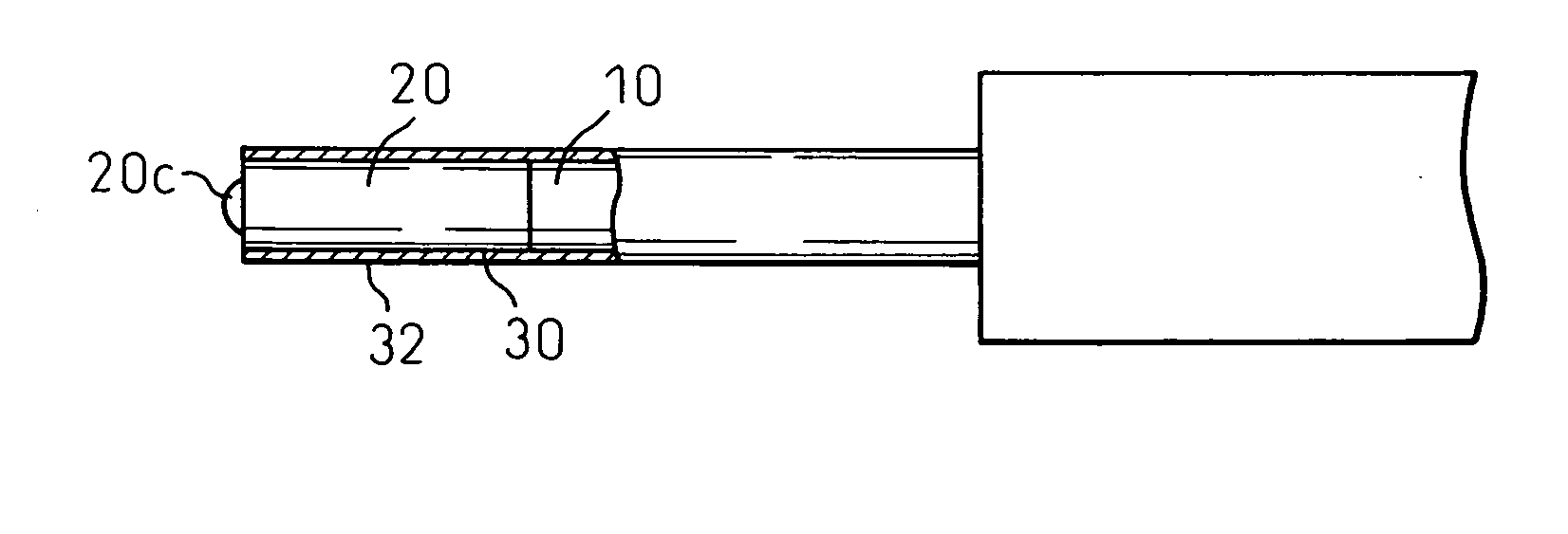
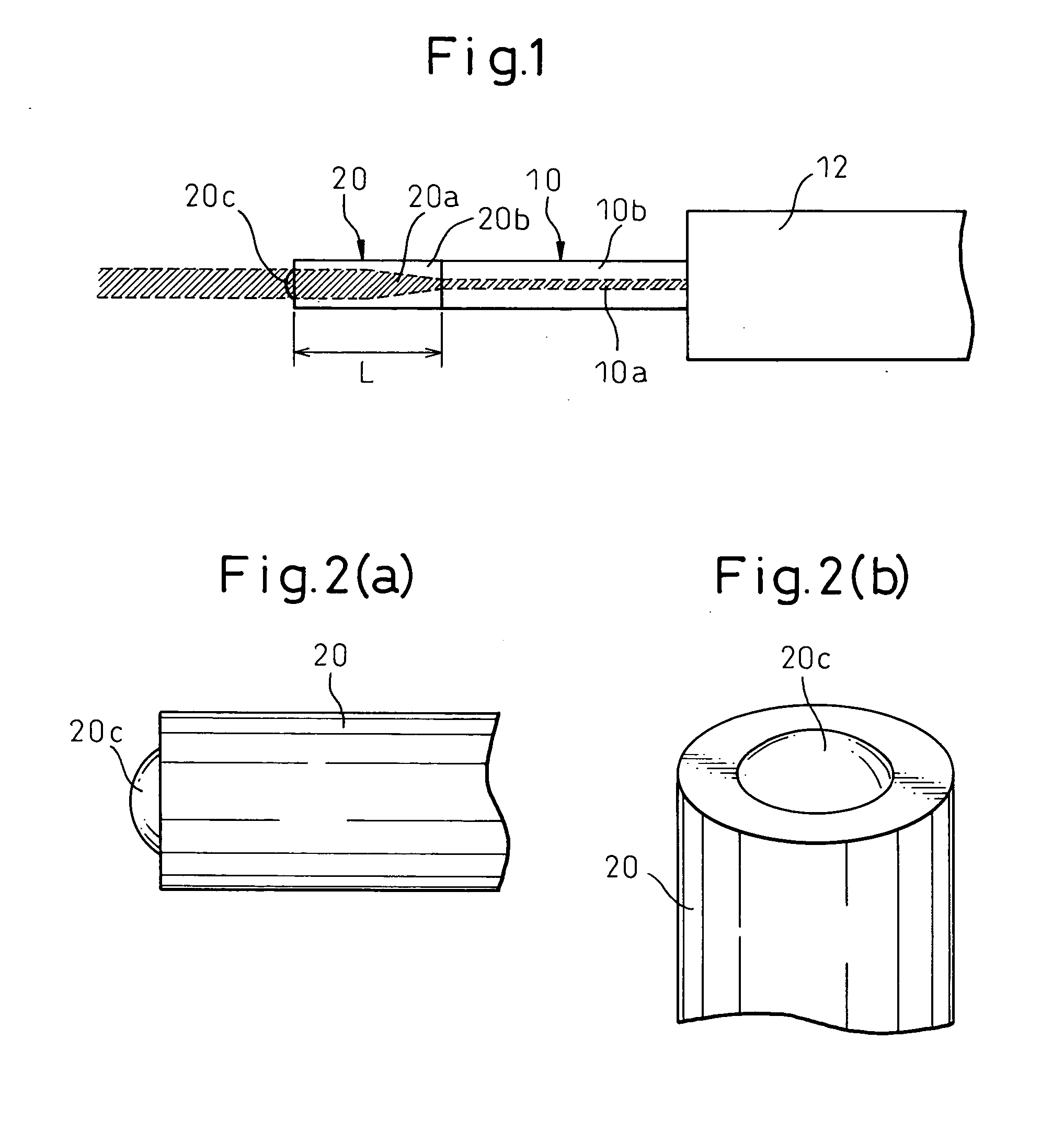
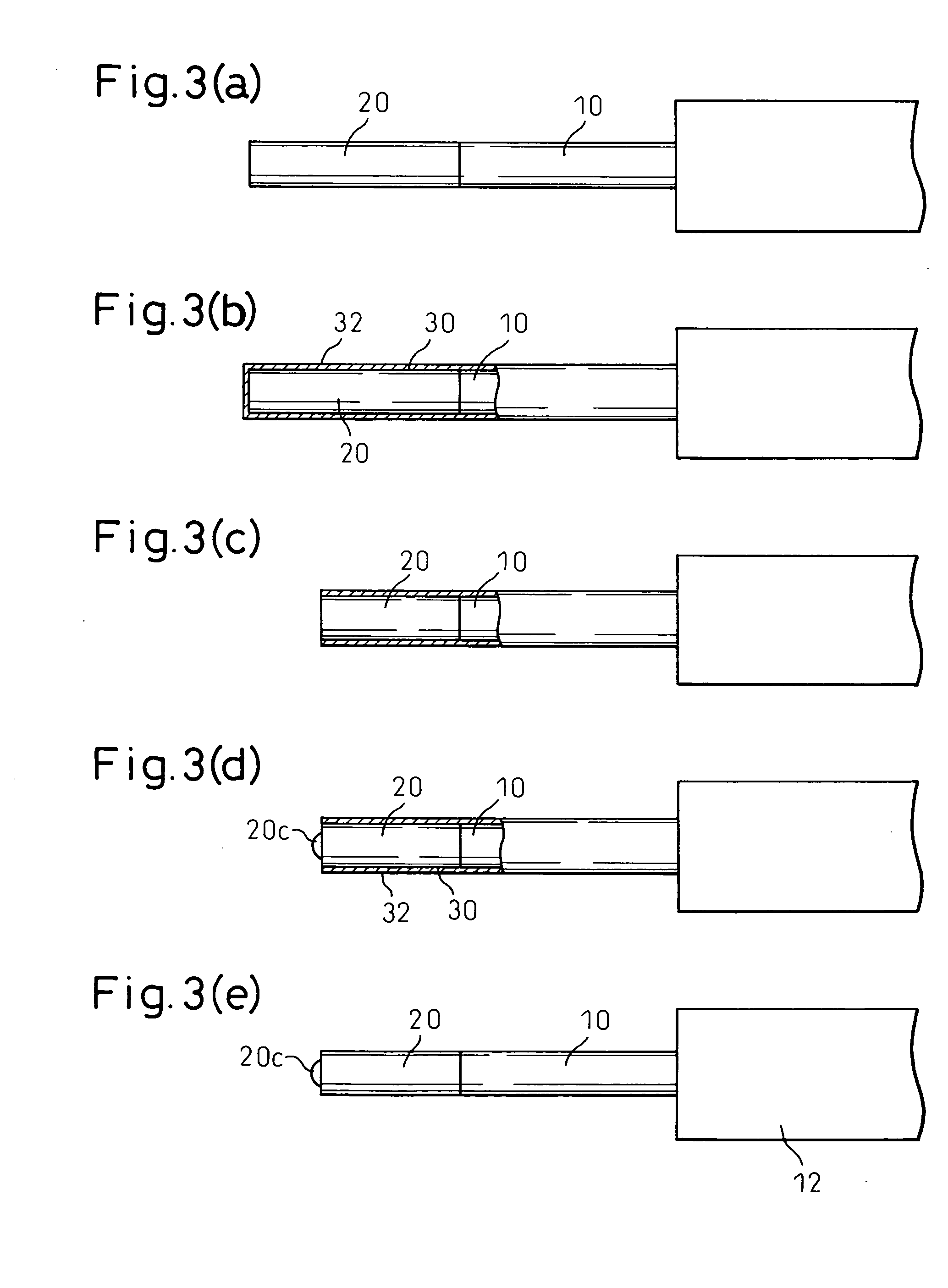
[0027]FIG. 1 is a schematic illustration showing an overall arrangement of the optical fiber collimator of the present invention. In the same manner as that of the optical fiber collimator shown in FIG. 4, the optical fiber collimator of the present invention is composed in such a manner that GI optical fiber 12 is fused to an end face of the single mode optical fiber 10. The characteristic of the optical fiber collimator of the present embodiment, which is different from the conventional optical fiber collimator, is that the hemispherical bulge portion 20c is formed on an end face of GI optical fiber 20.

[0028] FIGS. 2(a) and 2(b) are enlarged views showing a neighborhood of the end face of GI optical fiber 20. FIG. 2(a) is a side view, and FIG. 2(b) is a perspective view. In the circular end face region of GI optical fiber 20, the bulge portion 20a is f...


PUM


Abstract

An optical fiber collimator is provided in which the optical axis of a beam of light incident upon and emergent from the end face of the optical fiber collimator utilizing graded index (GI) optical fiber is made to perfectly agree with the axial direction of the optical fiber and further the optical fiber collimator is capable of obtaining a return loss characteristic. The optical fiber collimator comprises: a single mode (SM) optical fiber and GI optical fiber fused to an end face of SM optical fiber so that an optical axis of SM optical fiber is coincide with an optical axis of GI optical fiber to effect an optical transmission between these fibers; and GI optical fiber having a second end face provided with a bulge portion defining a smooth outer surface symmetrical with respect to the common optical axis of SM and GI optical fibers.

Description

TECHNICAL FIELD [0001] The present invention relates to an optical fiber collimator composed in such a manner that a graded index optical fiber (GIF) is fused to an end face of a single mode optical fiber (SMF), and light can be incident upon and emergent from an end face of the optical fiber in parallel with the axial direction of the optical fiber. The present invention also relates to a method of manufacturing the optical fiber collimator. BACKGROUND ART [0002] FIGS. 4(a) and 4(b) are views showing the constitution of an optical fiber collimator in which a graded index optical fiber (GI optical fiber) is utilized. This collimator is formed when GI optical fiber 20 (wick wire) of a predetermined length, by which a collimating action is generated, is fused to an end face of the single mode optical fiber 10 (wick wire). Reference numeral 12 is a coating portion for coating a wick wire of the single mode optical fiber 10. In this specification, “wick wire” refers to an optical fiber ...

Claims


Application Information

Patent Timeline
Patent Type & Authority Applications(United States)
IPC IPC(8): G02B6/02G02B6/255G02B6/26G02B6/32
CPCG02B6/0281G02B6/32G02B6/262G02B6/2551
Inventor TATEIWA, AKIHIKO
Owner SHINKO ELECTRIC IND CO LTD
Learn More