

Optical fiber, method for manufacturing same and optical transmission channel
a technology of optical fiber and manufacturing method, applied in the direction of cladded optical fiber, manufacturing tools, instruments, etc., can solve the problems of non-linearity and unsuitability of optical fiber for long-haul wdm optical transmission
- Summary
- Abstract
- Description
- Claims
- Application Information
AI Technical Summary
Benefits of technology
Problems solved by technology
Method used
Image

Examples
first embodiment
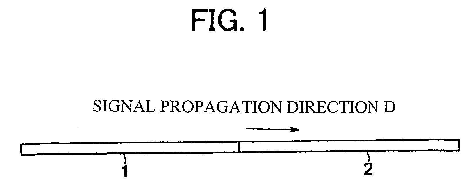
[0090] Description is made, as one embodiment of an optical fiber according to the present invention, about an optical fiber 1 provided at the anterior portion of a dispersion-managed optical transmission channel shown in FIG. 1, that is, WDM transmission single-mode optical fiber 1.
[0091] The dispersion-managed optical transmission channel shown in FIG. 1 comprises a combination of an optical fiber 1 provided at the anterior portion having an increased effective area (Aeff), positive chromatic dispersion and a positive dispersion slope and an optical fiber 2 provided at the posterior portion having negative chromatic dispersion and a negative dispersion slope to achieve low residual dispersion as a whole.
Configuration and Characteristics of Optical Fiber
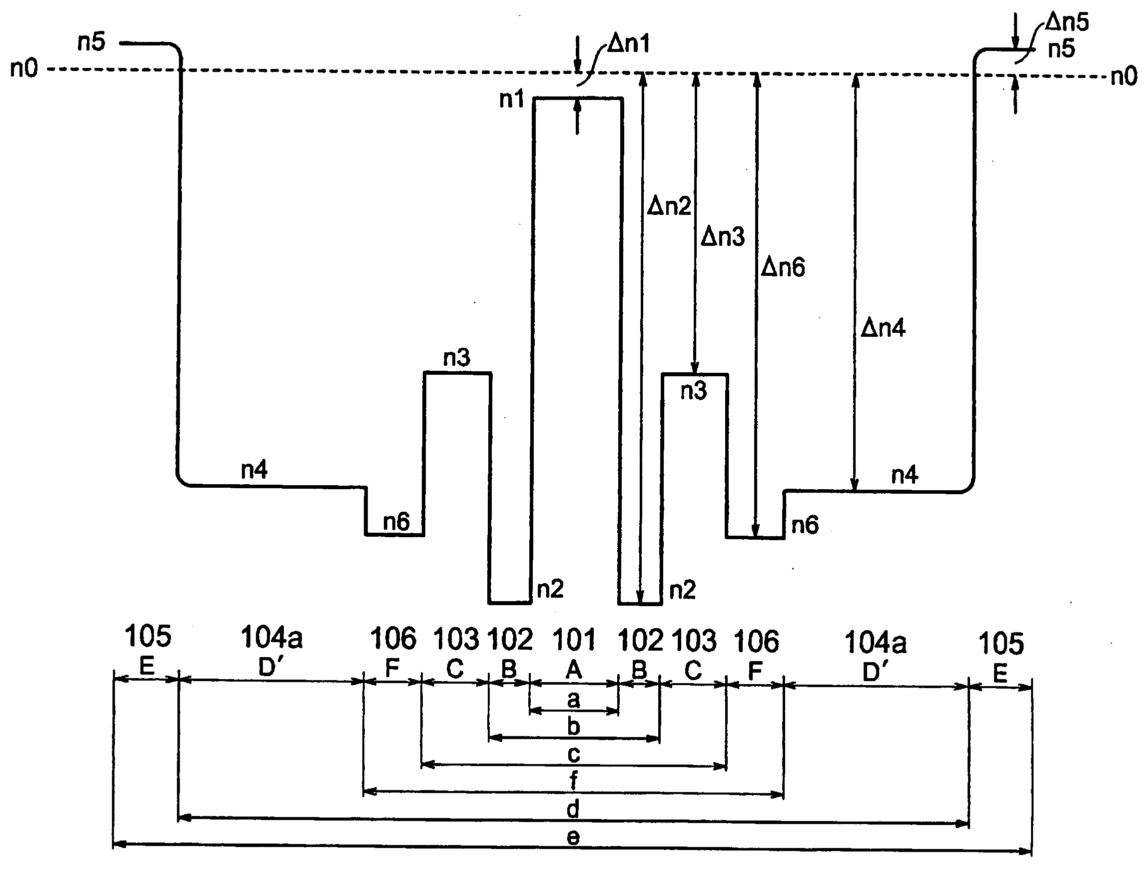
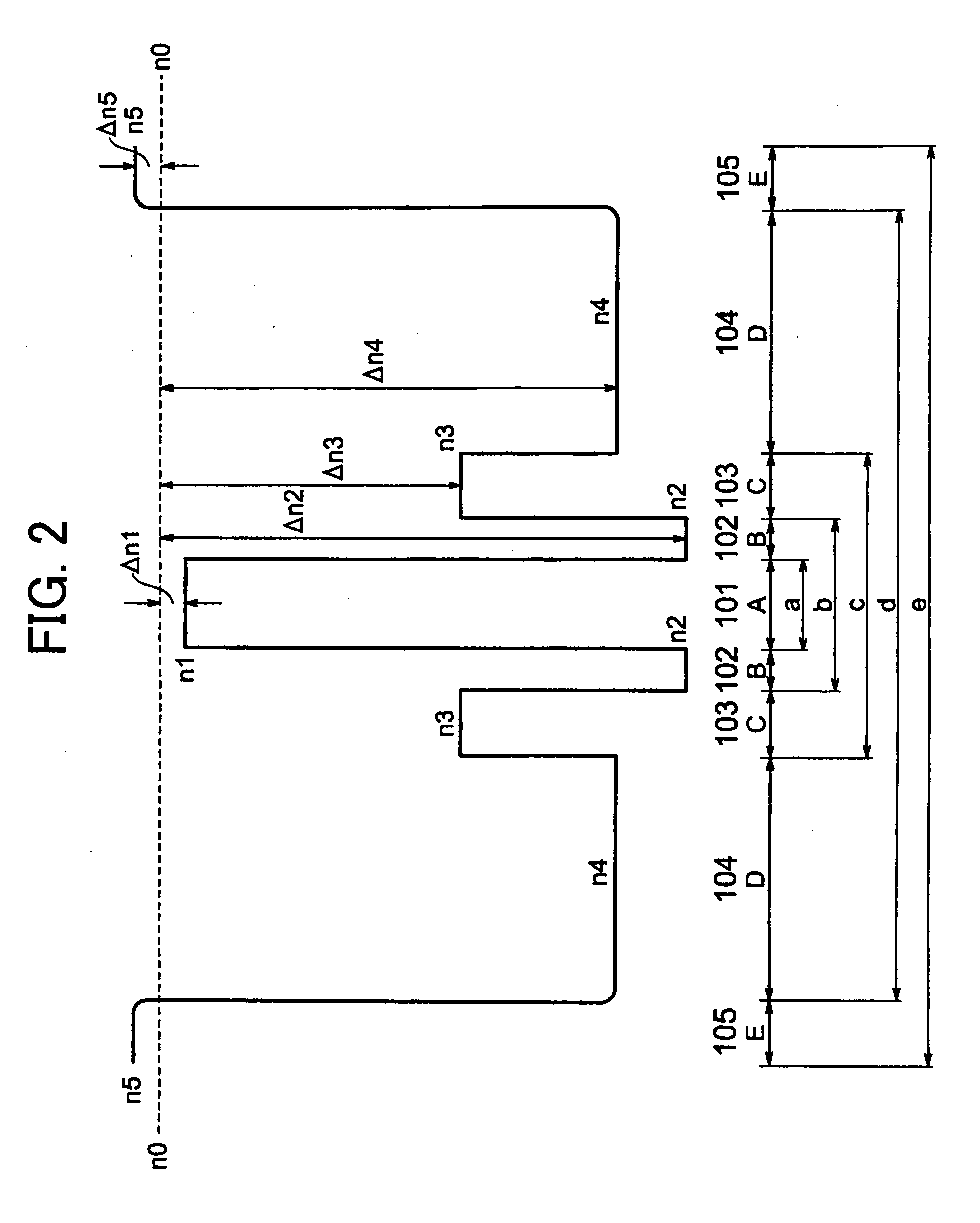
[0092]FIG. 2 shows a configuration of a WDM transmission single-mode optical fiber (SMF) 1 with zero dispersion wavelength in the vicinity of 1300 nm (1,3 μm), having an increased effective area (Aeff), positive chromatic disper...
example 1
[0157] In the example 1, three kinds of samples are prepared by the aforementioned manufacturing method, which samples having different germanium concentrations CGe (mol %) and fluorine concentrations CF (mol %) of the portions 101 through 104 of the optical fiber.
[0158] In this case, the refractive index differences Δn1 through Δn5 of the respective regions 101 through 105 of the optical fiber relative to the reference refractive index n0 of the silica glass which includes no dopant, the ratio b / a of the outer diameter b of the second region (B) 102 to the outer diameter a of the fist region (A) 101, and the ratio c / a of the outer diameter c of the third region (C) 103 to the outer diameter a of the first region (A) 101 are fixed as shown in the table 1 as above: Δn1=−0.02, Δn2=−0.41, Δn3=−0.25, Δn4=−0.30, Δn5=+0.03, b / a=1.30, and c / a=2.3375.
[0159] As to the samples 1 to 3, transmission characteristics including the transmission loss at 1,550 nm, the chromatic dispersion at 1,550...
example 2
[0164] In this example 2, three samples A to C are prepared, which samples having different relative refractive index differences Δn2 through Δn4 of the respective regions 102 through 104 of the optical fiber, different ratios b / a of the outer diameter b of the second region (B) 102 to the outer diameter a of the first region (A) 101, and different ratios c / a of the outer diameter c of the second region (C) 103 to the outer diameter a of the first region (A) 101.
[0165] Then, as to the samples 1 to 3, just like in the example 1, transmission characteristics including the transmission loss at 1,550 nm, the chromatic dispersion at 1,550 nm, and the dispersion slope at 1,550 nm, the effective area Aeff at 1,550 nm, the cable cutoff wavelength λcc and the macrobending loss on mandrel having an outer diameter of 20 mm (20 mmφ) were measured, which results are shown in the table 4. Also listed in the table 4 are above-mentioned desired characteristic requirements for comparison.
TABLE 4S...
PUM
| Property | Measurement | Unit |
|---|---|---|
| Fraction | aaaaa | aaaaa |
| Time | aaaaa | aaaaa |
| Time | aaaaa | aaaaa |
Abstract
Description
Claims
Application Information