Multi-stage vacuum pump

Inactive Publication Date: 2005-04-28
IND TECH RES INST
View PDF6 Cites 36 Cited by
  • Summary
  • Abstract
  • Description
  • Claims
  • Application Information

AI Technical Summary

Benefits of technology

[0009] It is the main object of the present invention to provide a multi-stage vacuum pump, which has reduced outer diameter and volume. It is another object of the present invention to provide a multi-stage vacuum pump, which has a reduced weight to lower the manufacturing cost. According to one aspect of the present invention, the multi-stage vacuum pump is comprised of a plurality of casings, a plurality of partition plates, a mover module, and a synchronizer gear module. The casings are axially connected in series, each defining a compression chamber inside thereof. The partition plates each having a predetermined wall thickness, and each respectively mounted between two adjacent casings of the casings to separate the compression chambers of the two adjacent casings. Each partition plate has two through holes. The mover module comprises two parallel shafts respectively extended through the two through holes of each of the partition plates, and a plurality of rotors symmetrically formed integral with the two parallel shafts respectively and arranged in pairs, wherein each pair of two adjacent rotors of the rotors received in one corresponding compression chamber of the casings for compressing air. The synchronizer gear module adapted to rotate the shafts and the rotors synchronously.
[0010] The main feature of the present invention is the design of the partition plates. Each partition plate has

Problems solved by technology

Due to this drawback, the size and weight of the multi-st

Method used


Image

  • Multi-stage vacuum pump
  • Multi-stage vacuum pump
  • Multi-stage vacuum pump

Examples


Embodiment Construction

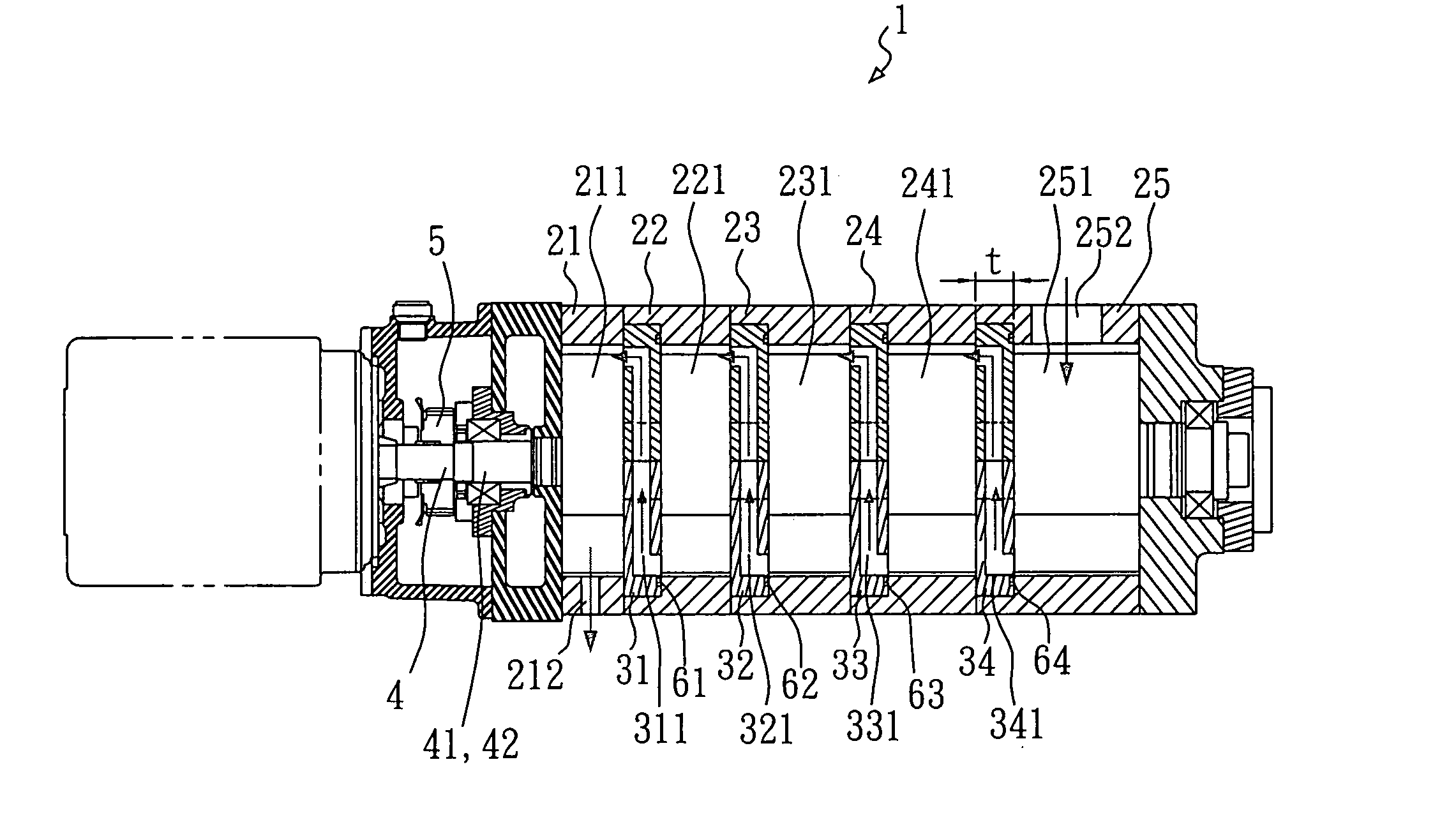
[0019] Referring to FIG. 4, a multi-stage vacuum pump 1 is shown comprised of a plurality of casings 21˜25, a plurality of partition plates 31˜34, and a mover module 4. The casings 21˜25 are axially connected in series, each defining a respective compression chamber 211˜251 inside thereof. The partition plates 31˜34 each having a predetermined wall thickness t, and each respectively mounted between two adjacent casings 21˜25 to separate the compression chambers 211˜251 from one another.

[0020] Referring to FIGS. 5 and 6 and FIG. 4 again, the partition plates 31˜34 are identical. FIGS. 5 and 6 show only one partition plate 34 for explanation. The partition plate 34 has two through holes 301 and 302. The aforesaid mover module 4 comprises two parallel shafts 41 and 42 suspended in the compression chambers 211˜251 and respectively extended through the two through holes 301 and 302 of every partition plate 31˜34, a plurality of rotors 411 and 421 respectively symmetrically formed integr...


PUM


Abstract

A multi-stage vacuum pump includes a plurality of casings connected in series and each casing defining a respective compression chamber, a plurality of partition plates each set in between each two casings. When compressed by rotors at shafts in one compression chamber, compressed air passes through the air path formed in the corresponding partition plate to the next compression chamber for further compression, and finally compressed air passes to the last compression chamber through the air path formed in the last partition plate. Because the invention is designed to let compressed air directly pass through the air path in each partition plate, the outer diameter and volume of the multi-stage vacuum pump can be minimized to reduce the weight and the manufacturing cost.

Description

BACKGROUND OF THE INVENTION [0001] 1. Field of the Invention [0002] The present invention relates to a vacuum pump and, more particularly, to a multi-stage vacuum pump, which has a small outer diameter and reduced volume and weight and, which is inexpensive to manufacture. [0003] 2. Description of Related Art [0004] Regular equipment for clean manufacturing process, for example, equipment for depositing process, etching process, ion implanting process in semiconductor manufacturing commonly use a vacuum system to provide a proper vacuum environment for operation. [0005] In the aforesaid vacuum system, a vacuum pump is used to achieve the desired vacuum effect. Therefore, the quality of the vacuum pump determines the achievement of the vacuum system. [0006]FIG. 1 is a sectional view of a multi-stage vacuum pump according to the prior art. According to this design, the multi-stage vacuum pump 9 is comprised of a plurality of casings 911˜915 and a plurality of partition plates 921˜924 ...

Claims


Application Information

Patent Timeline
IPC IPC(8): F04C18/08F04C18/12F04C23/00
CPCF04C18/086F04C2220/12F04C23/001F04C18/126
Inventor LIU, MING-HSINFANG, HONG-SHENGSHEN, TEAN-MUCHIEN, JUNG-CHENCHEN, JIUN-HUNG
Owner IND TECH RES INST
Why Eureka
Try Eureka