

Fuel reforming system and fuel cell system having same
- Summary
- Abstract
- Description
- Claims
- Application Information
AI Technical Summary
Benefits of technology
Problems solved by technology
Method used
Image

Examples
embodiment 1
[0039] Embodiment 1
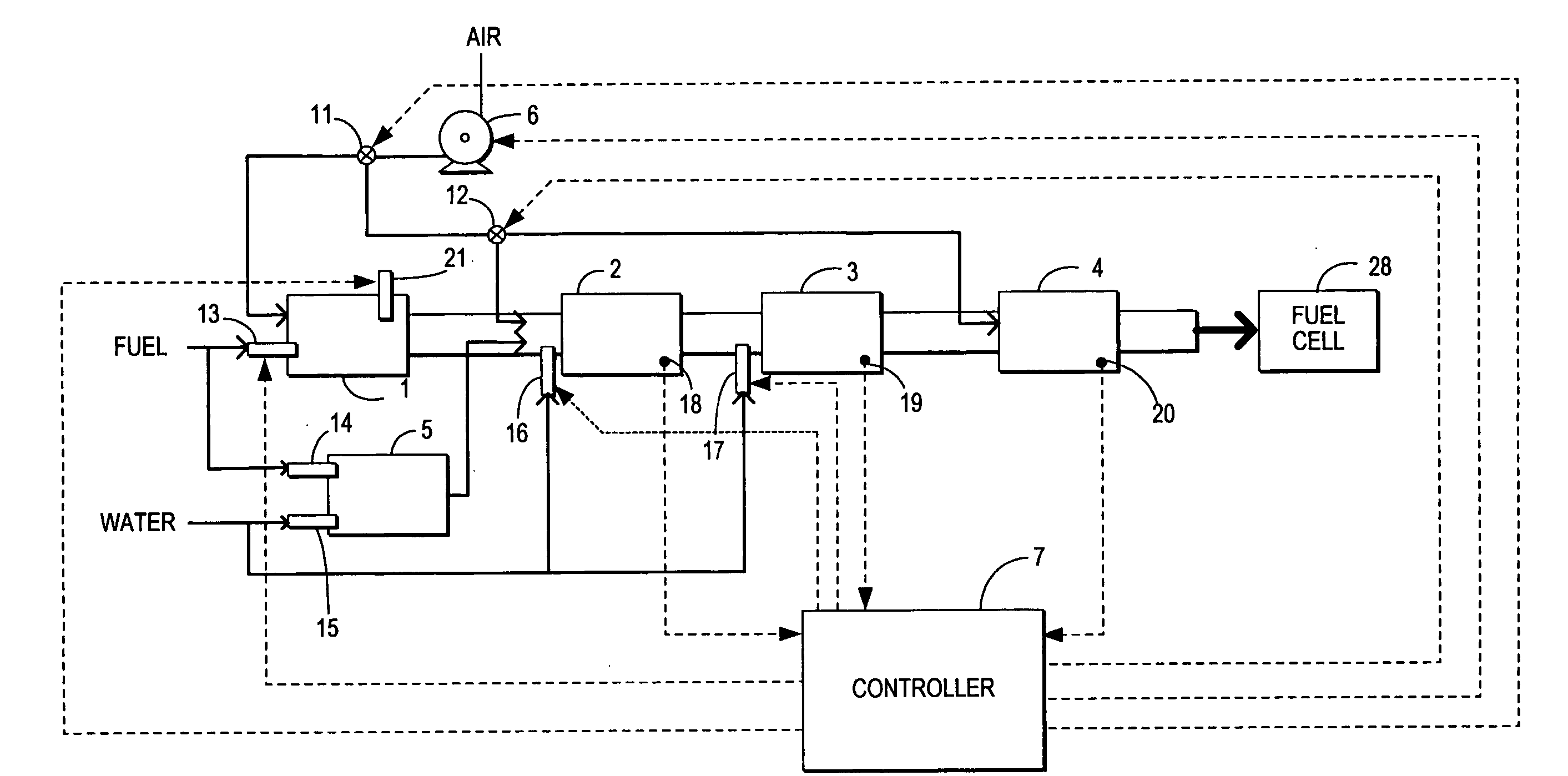
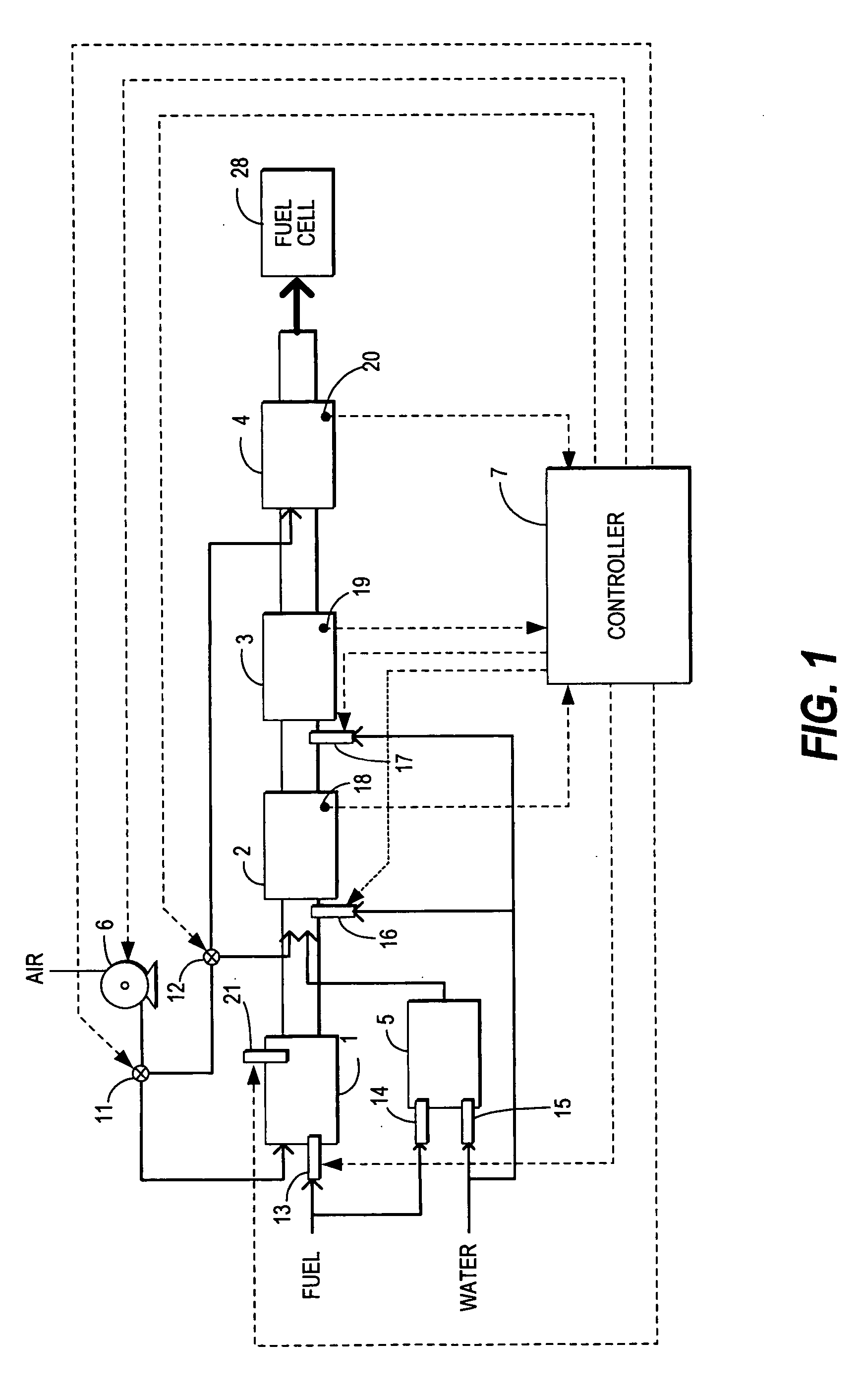
[0040]FIG. 1 of the drawings shows the construction of the fuel cell system of a first embodiment. The fuel cell system includes a fuel cell 28 and a fuel reforming system (i.e. other components in FIG. 1). A startup burner 1 generates combustion gas for warming up a reformer (reforming reactor 2, shift reactor 3, CO removal reactor 4) of the fuel reforming system when the fuel cell system starts. When fuel is supplied from a fuel injection valve 13 and air is supplied through an air feeder 6 (e.g. blower, compressor, etc.) to the startup burner 1, fuel is ignited by an ignition source 21 such as a spark plug or a glow plug. A combustion air-fuel ratio is set to be leaner than the stoichiometric air-fuel ratio. Taking account of the heat-resisting properties and exhaust performance of the fuel reforming system, the air-excess ratio λ is set in the region of 2-5. The air-excess ratio λ is the ratio of the supply air amount to the air amount theoretically required t...
embodiment 2
[0071] Embodiment 2
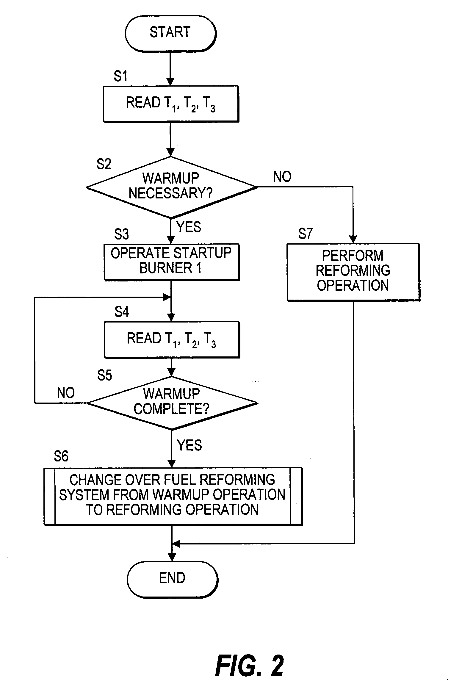
[0072] The construction of the fuel cell system of the second embodiment is identical to that of the first embodiment shown in FIG. 1. The control performed by the controller 7 is essentially identical to that of the first embodiment shown in FIG. 2, except that the processing in the step S6 differs from that of the first embodiment.
[0073] The operation change-over control from the warmup operation to the reforming operation in the step S6, will now be described referring to the flowchart shown in FIG. 5.
[0074] In a step S6-11, the air feeder 6 is stopped at the same time as the fuel injection valve 13 is stopped. The production of combustion gas is stopped by stopping the supply of fuel and air to the startup burner 1. In a step S6-12, the water feeder 16 is operated, water is supplied to the reforming reactor 2, and a water vapor layer is formed upstream of the lean combustion gas. In a step S6-13, it is determined whether or not the water supply amount Qw fro...
embodiment 3
[0079] Embodiment 3
[0080]FIG. 7 shows the construction of the fuel cell system of the third embodiment. In the third embodiment, water is injected upstream of the shift reactor 3 from the water feeder 17. The water feeder 16 is omitted. When the fuel cell system starts, the control shown in FIG. 8, which is identical to that of the first embodiment, is thereby performed not using the water feeder 16, but using the water feeder 17, the timing chart when there is a shift from the warmup operation to the reforming operation being identical to that of FIG. 4.
[0081] According to the third embodiment, when there is a shift from the warmup operation to the reforming operation, nonflammable fluid is supplied by the water feeder 17 between the reforming reactor 2 and the shift reactor 3. Thus, a shift catalyst which has a lower heat resistance than the reforming reactor 2, and whose temperature tends to rise more easily above a permitted temperature, can be sufficiently cooled and protected...
PUM
 Abstract
Description
Claims
Application Information