
Network communications system

a network communication and system technology, applied in the field of data communication networking, can solve the problems of unable to seamlessly integrate existing lan hubs and switches into a conference room or similar environment, and limiting network access to only one user at a time, so as to facilitate the addition of network connectivity. the effect of inexpensiv

Inactive Publication Date: 2005-04-28
INTEL CORP
View PDF23 Cites 11 Cited by
  • Summary
  • Abstract
  • Description
  • Claims
  • Application Information

AI Technical Summary

Benefits of technology

[0005] Broadly, the present invention provides a network communications system for efficiently connecting a plurality of computer systems with a local area network in a small work area environment such as a conference room. The system includes a plurality of retractable cables connectable to a corresponding number of computers that eliminate the inevitable tangle of network cables that occur with existing hub and switch products. Further, the system facilitates the inexpensive addition of network connectivity to a conference room environment.

Problems solved by technology

The availability of networking connections in conference rooms has heretofore been limited because of the high cost of custom conference room furniture with integrated LAN jacks.
Thus, conference rooms are often equipped with only one LAN wall jack thereby limiting network access to only one user at a time.
In addition, existing LAN hubs and switches are not designed to be seamlessly integrated into a conference room or similar environment.
Thus, placing such a LAN interconnection apparatus in a conference room requires many individual network cables to connect users' computers to the apparatus.
Conference rooms so equipped are often plagued with a tangle of unsightly cables and sometimes cables are removed from the room.

Method used


Image

  • Network communications system
  • Network communications system
  • Network communications system

Examples


Embodiment Construction

[0028] By way of example, the invention will be described with reference to the widely used 10 / 100 Mbps Ethernet local area networks (LANs) typically found in workplace environments. Such Ethernet LANs conform to the IEEE 802.3, 802.3u and 802.3x network standards which are incorporated herein by reference.

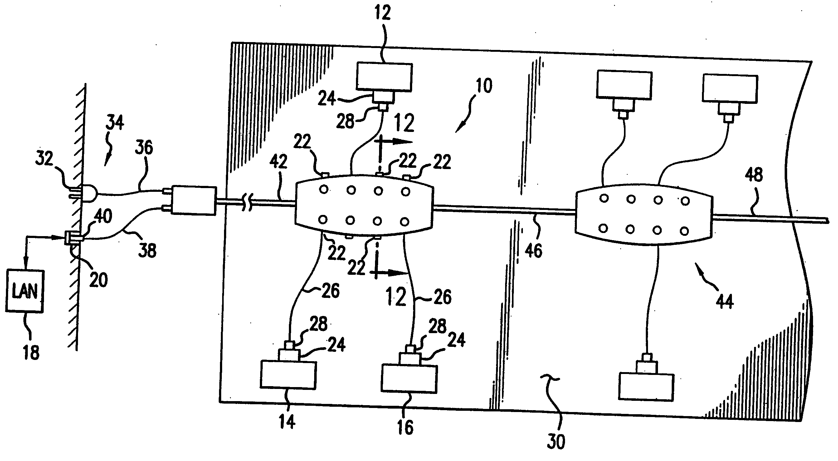
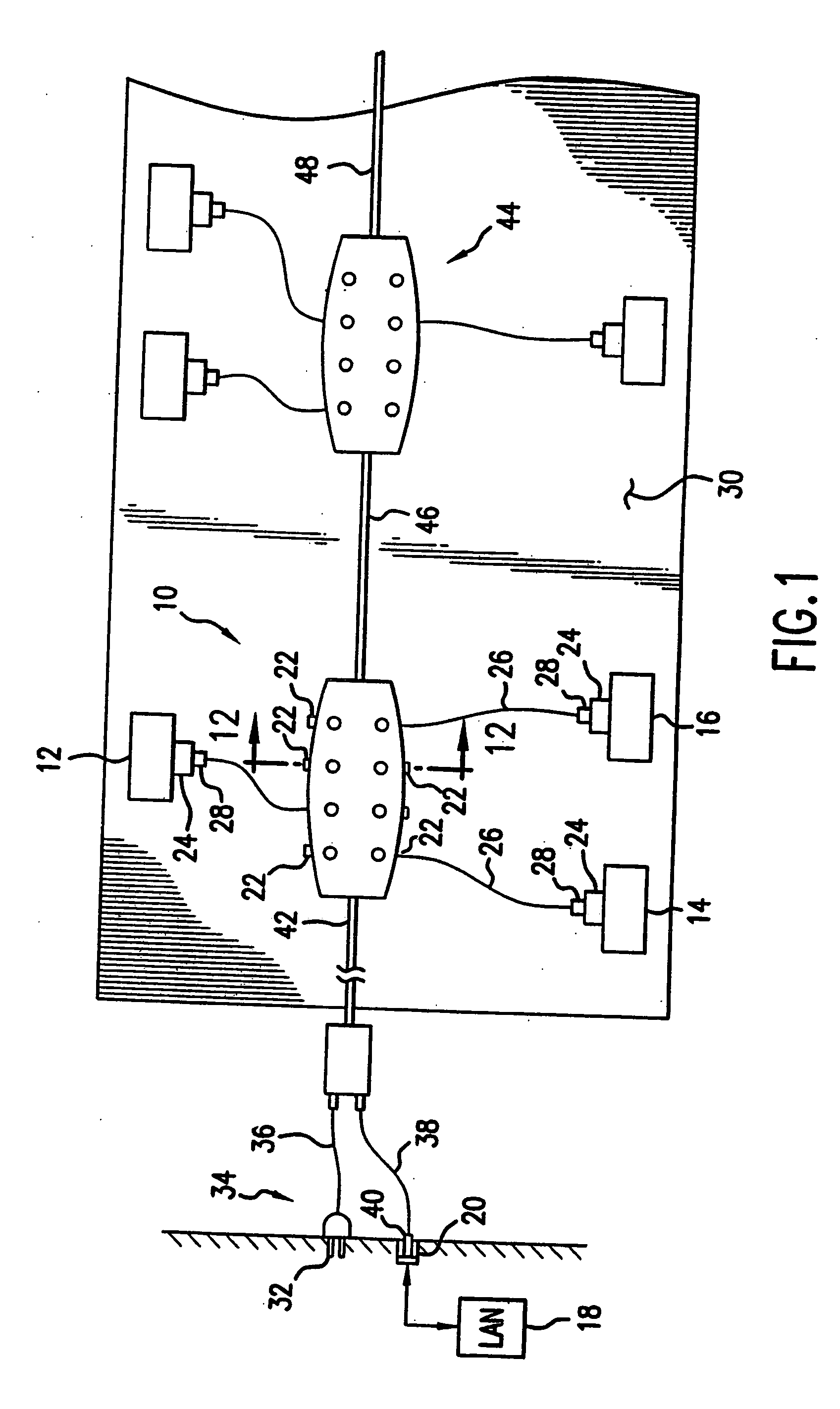
[0029] Referring first to the schematic representation of FIG. 1, there is shown a network communications system 10 for connecting, for example, a plurality of portable computers 12, 14 and 16 to each other and to an Ethernet local area network 18 via an RJ-45 wall jack 20. The specific embodiment of the system 10 shown in FIG. 1 has eight (8) client or computer ports 22 for connecting as many computers.

[0030] The computers 12, 14 and 16 typically comprise notebook or handheld computers provided with network interface cards or adapters 24. Examples of such adapters 24 are the Ethernet PC Cards and Ethernet / Modem Combo PC Cards manufactured by Xircom, Inc., Thousand Oaks, Calif. ...


PUM


Abstract

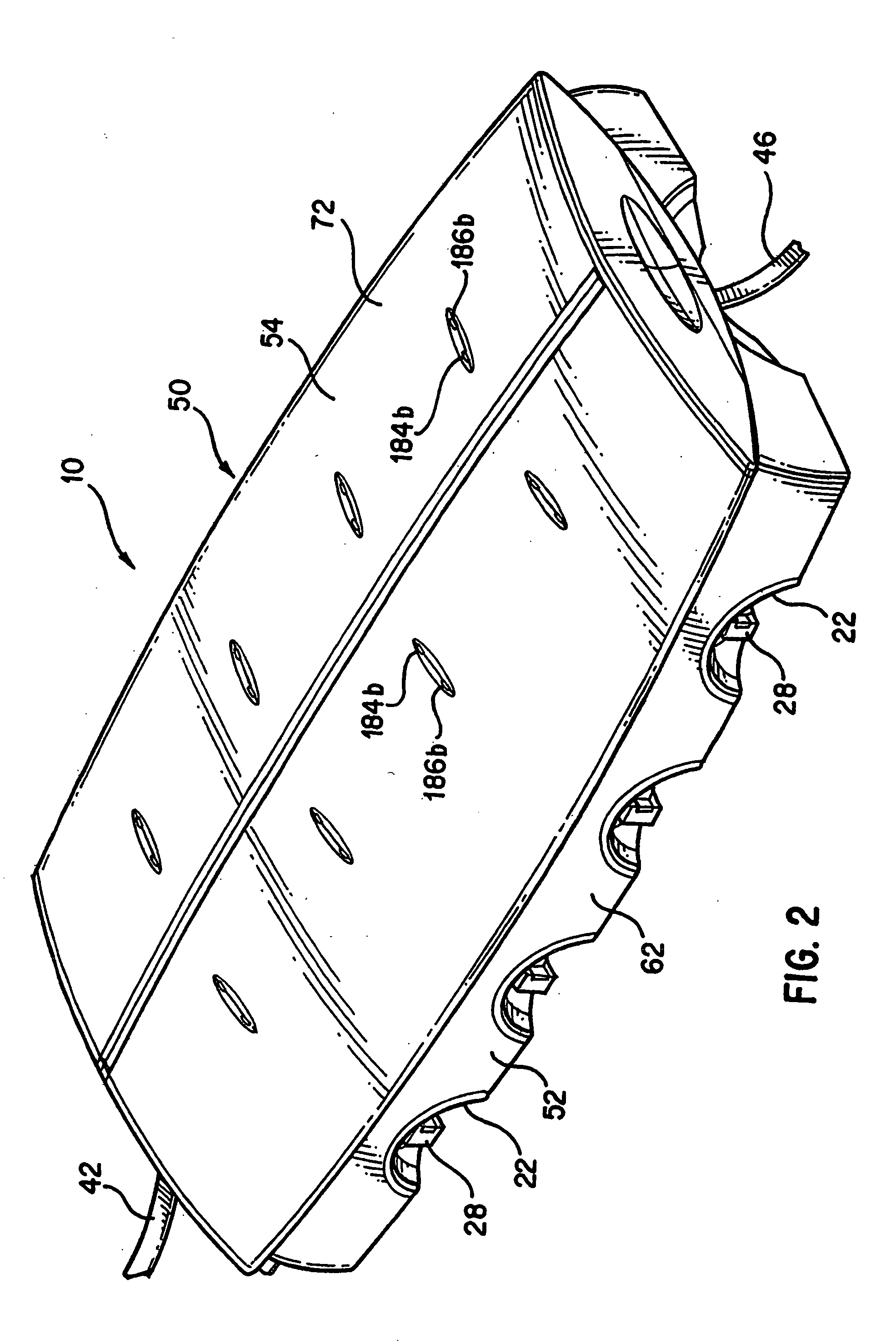
A network communications system is provided for allowing a group of computer users in a conference room or similar small work environment to access an Ethernet local area network (LAN) and to provide peer-to-peer group networking without connection to a backbone network. The system includes multiple (for example, 4 or 8) client computer ports each including a removable spring loaded cable dispenser carrying an extendible / retractable Category 5 LAN cable terminated with an RJ-45 plug for connection to a client computer's network adapter. Combined power / Ethernet LAN cables connect the system to an enterprise network and to a source of electrical power, and permit cascading of up to three 8-port systems. In use, a computer user pulls out the cable from one of the client ports and inserts the RJ-45 plug into the RJ-45 jack on the network adapter carried by the computer. After completion of the networking session, the user unplugs the cable which is automatically retracted by the spring loaded cable reel. A cable management system is thereby provided which eliminates the tangle or clutter of multiple cables encountered in existing systems.

Description

CROSS REFERENCE TO RELATED APPLICATIONS [0001] This divisional application claims the benefit of U.S. patent application Ser. No. 09 / 534,888 for Network Communications System, filed Mar. 24, 2000, Assignee Intel Corporation.FIELD OF THE INVENTION [0002] The present invention relates generally to data communications networking and particularly to a network communications system allowing a group of computer users in a conference room or similar small work area to access a local area network (LAN) and to provide peer-to-peer group networking and resource sharing without accessing the LAN. BACKGROUND OF THE INVENTION [0003] The widespread use of notebook and handheld computer systems in business environments has created a need for informal network access and information sharing. Mobile users require constant access to the company network for E-mail, internet and intranet services. Small workgroups of mobile notebook and handheld computer users often assemble for a meeting or a joint tas...

Claims


Application Information

Patent Timeline
Patent Type & Authority Applications(United States)
IPC IPC(8): H01R13/72H02G11/02
CPCH01R13/72H02G11/02H01R2201/06
Inventor LAITY, IANBAUDER, JAMES R.MCLINN, FRANKLIN E.
Owner INTEL CORP
Learn More