Spinal bone chisels

a technology of spine bone chisels and spine implants, which is applied in the field of spine bone chisels and the field of spinal disc space preparation, can solve the problems of lack of versatility in cutting spinal material from different adjacent areas

Inactive Publication Date: 2005-04-28
OSTEOTECH INC
View PDF25 Cites 116 Cited by
  • Summary
  • Abstract
  • Description
  • Claims
  • Application Information

AI Technical Summary

Benefits of technology

[0095] In a further aspect, the step of removing the second portion of material further includes the second portion of material being less distance to a longitudinal axis of the shank than the first portion of material such that the first cutting edges are positioned a first distance from the longitudinal axis to remove the first portion of material and the second cutting edges are positioned a second distance from the longitudinal axis which is less than the first distance and positions the at least one second cutting edge to remove the second portion of material.

Problems solved by technology

A drawback of present cutting instruments is the lack of versatility in cutting spinal material from different adjacent areas.

Method used


Image

  • Spinal bone chisels
  • Spinal bone chisels
  • Spinal bone chisels

Examples


Embodiment Construction

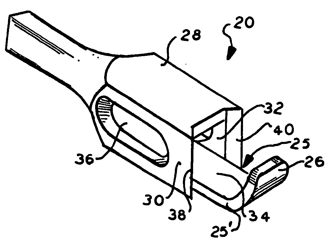
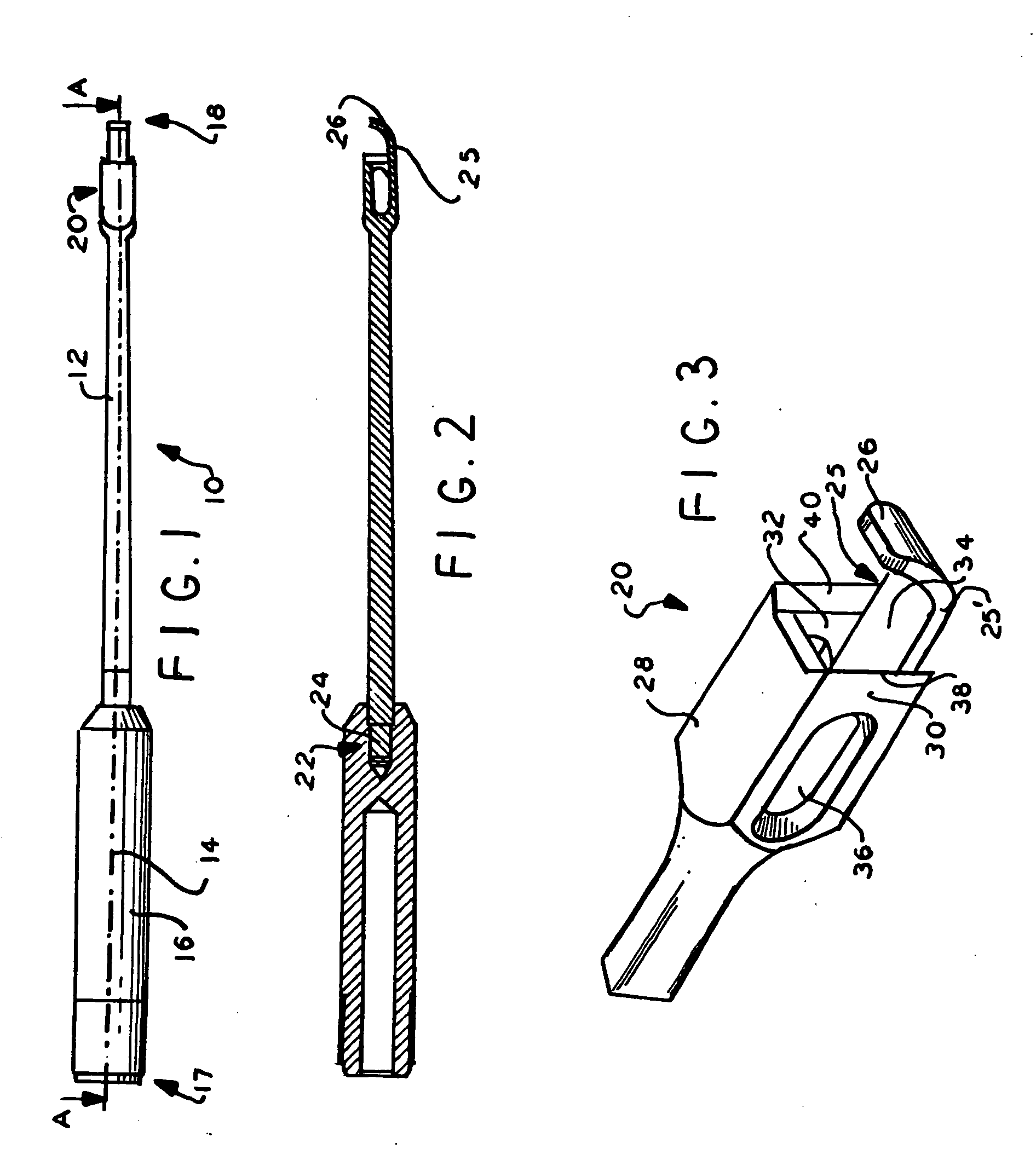
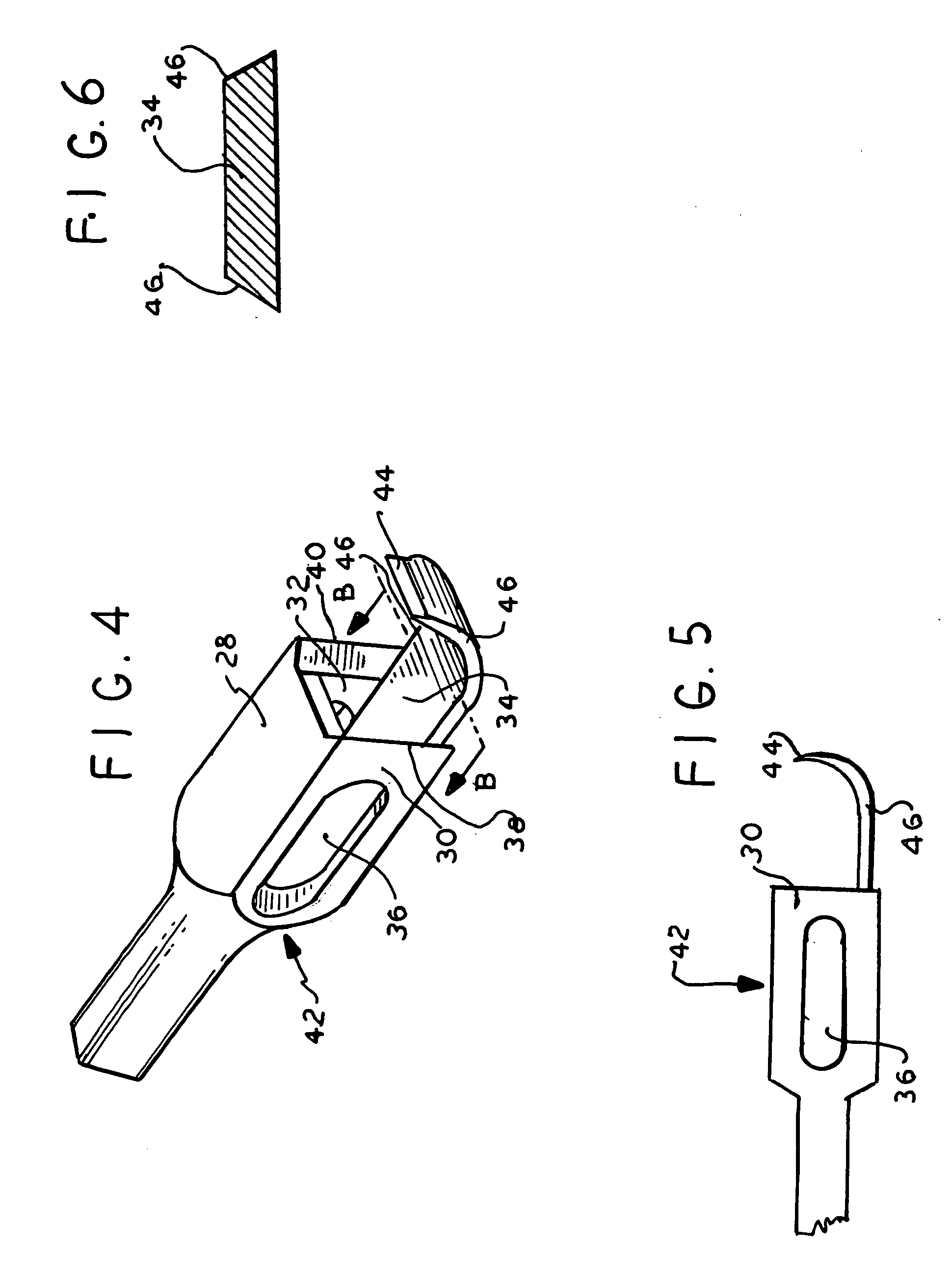
[0257] In FIG. 1, chisel instrument 10 comprises an elongated shank 12 defining a longitudinal axis 14, a handle 16 attached to the shank 12 at a proximal end 17, and a cutting head 20 attached to the shank at a distal end 18. The handle 16 (shown in FIGS. 1 and 2) may have a bore 22 in which the shank 12 is inserted and attached to the handle. The shank 12 may include a stud 24 for receiving the handle. The shank 12 may be press fit into the handle bore 22 or may be threaded to the handle at bore 22 or may be bonded to the handle such as by welding. The handle 16 is elongated and extends along the longitudinal axis 14. The handle 16 has a transverse dimension greater than that of the shank 12 to permit ease of gripping by a surgeon during use. The handle and shank may be formed of stainless steel, for example, and preferably is circular cylindrical or, in the alternative may have other cross section shapes such as square or rectangular, for example. The handle 16 may also have flat...


PUM


Abstract

A chisel with distal cutting edges, used to form channels in adjacent vertebrae, includes a shank having a longitudinal axis and a cutting head coupled to the distal end of the shank. The cutting head includes distal cutting edges, which may be linear, arcuate, or V-shaped, and a guide member, which may be hollow or formed as two spaced members, to guide the chisel into the disc space to uniformly chisel both adjacent vertebrae simultaneously to partially form a channel in the vertebrae. The guide member and cutting head may have openings for distributing cut debris to the top and bottom surfaces of the head. The guide member may also include distal transverse, longitudinal side and/or vertical cutting edges, some of which may be in stepped relationship, for further cutting the endplates and removing disc material from between adjacent vertebrae, and for scraping of endplates. Other embodiments are disclosed.

Description

[0001] This application claims the benefit of provisional application Ser. No. 60 / 513,893 filed Oct. 23, 2003, incorporated by reference herein in its entirety.[0002] This invention relates to spinal implant chisel tools and method of preparing the spinal disc space, and more particularly to spinal chisel instruments having various cutting edges for preparing the intervertebral disc space for implants. CROSS REFERENCE TO RELATED APPLICATIONS AND PATENTS [0003] Of interest are commonly owned copending provisional application Ser. No. 60 / 397,232 filed Jul. 19, 2002 in the name of David Chow et al., and PCT application Serial No. PCT / US03 / 21967 filed Jul. 11, 2003, entitled Spinal Implant Insertion Adjustment Instrument and Implants for use therewith, in the name of Osteotech Inc., all incorporated by reference herein. [0004] During spinal surgery, the surgeon may approach the spine from a variety of different orientations. One orientation uses the posterior approach, another uses the ...

Claims


Application Information

Patent Timeline
Patent Type & Authority Applications(United States)
IPC IPC(8): A61B17/16A61B17/32
CPCA61B17/1604A61B2017/00261A61B17/320016A61B17/1671
Inventor MARTZ, ERIKMILLETS, JOEL
Owner OSTEOTECH INC
Why Eureka
Try Eureka