Angled tissue cutting instruments and method of fabricating angled tissue cutting instruments having flexible inner tubular members of tube and sleeve construction

a technology cutting instruments, which is applied in the field can solve the problems of ineffective transmission of torque to the cutting configuration, the inability of angled tissue cutting instruments utilizing this type of flexible inner tubular members to operate in both forward and reverse rotational directions, and the addition of spirals to the flexible inner tubular members. it can prevent suction in the lumen and increase the structural strength of the flexible inner tubular members

Active Publication Date: 2005-04-28
MEDTRONIC XOMED INC
View PDF30 Cites 109 Cited by
  • Summary
  • Abstract
  • Description
  • Claims
  • Application Information

AI Technical Summary

Benefits of technology

[0024] The present invention has as another object to eliminate spaces through the overall wall thickness of flexible regions of the flexible inner tubular members of angled tissue cutting instruments.
[0025] A still further object of the present invention is to prevent suction in the lumen of a flexible inner tubular member of an angled tissue cutting instrument from being lost through the wall of the flexible inner tubular member along a flexible region thereof.
[0026] Moreover, it is an object of the present invention to prevent irrigating fluid flowing between the angled outer tubular member and the flexible inner tubular member of an angled tissue cutting instrument from being drawn into the lumen of the flexible inner tubular member through the wall of the flexible inner tubular member along a flexible region thereof.
[0027] Still a further object of the present invention is to increase the structural strength of the flexible inner tubular members of angled tissue cutting instruments.

Problems solved by technology

The angled configuration of the outer member can be formed by various angles, bends or curves, as limited by the ability of the flexible inner tubular member to bend.
Accordingly, angled tissue cutting instruments utilizing this type of flexible inner member cannot be operated in both forward and reverse rotational directions.
Each spiral adds material and labor costs to the flexible inner tubular member and, therefore, to the angled tissue cutting instrument.
Another disadvantage of the flexible inner tubular member used in the Trott instrument is that the neck portions tend to stiffen the composite spiral in the vicinity of the cutting tip thereby preventing the inner member from bending adjacent the cutting tip.
In addition, it is possible for the separate components to become detached from one another during use such that torque can no longer be effectively transmitted to the cutting configuration.
The drive shaft of the Shturman patent is referred to in the Shturman et al patent as being difficult and time-consuming to manufacture.
The drive shaft of the Shturman et al patent has its outer helical layer made up of a single wire and its inner helical layer made up of a plurality of wires, which must all be wound around a forming mandrel so that the drive shaft requires many parts and is still difficult and time-consuming to manufacture.
Flexible shafts or tubular members comprising two layers of helical windings or coils have many of the same disadvantages as flexible tubular members that have three helical windings or coils.
Another disadvantage associated with the use of helical coils or springs to transmit torque while imparting flexibility is that spaces or gaps between the coils may be presented along the body of the flexible inner tubular member which allow suction in the lumen or aspiration passage of the inner tubular member to be dissipated such that less suction is applied at the aspiration port for reduced aspiration efficiency.
A weakened suction force or vacuum in the aspiration passage and / or at the aspiration port may lead to clogging or jamming of the tissue cutting instrument due to tissue build-up.
Clogging or jamming of tissue cutting instruments due to tissue build-up undesirably leads to the need for frequent cleaning or substitution of the instruments during use, which is time consuming and increases the duration of the surgical procedure to the detriment of the patient and the surgeon.
Loss of irrigation efficiency is another problem where spaces are presented between the coils, since irrigating fluid flowing between the outer and inner members may be drawn through the spaces into the aspiration passage.
An additional drawback of helical coils or springs is the tendency of the coils or springs to require tightening or preloading.
In the angled tissue cutting instruments described in the aforementioned Krause et al patents, the inner tubes have discrete, unconnected apertures or slots formed therein such that torque transmission is limited.
The flexible tube may not be well suited for use as a rotatable inner tubular member of a surgical cutting instrument since its torque capabilities may be limited to relatively low single direction and bidirectional rotational speeds.
The use of multiple spiral wrap layers over the helical cut reduces but does not eliminate the possibility of suction being lost from the lumen of the inner tube and / or irrigating fluid entering into the lumen of the inner tube since the helical cut and spiral wraps still present spaces for fluid flow between the outside and the inside of the tubular member.
However, each spiral wrap layer adds material and labor costs to the flexible inner tubular member and, therefore, to the angled tissue cutting instrument.

Method used


Image

  • Angled tissue cutting instruments and method of fabricating angled tissue cutting instruments having flexible inner tubular members of tube and sleeve construction
  • Angled tissue cutting instruments and method of fabricating angled tissue cutting instruments having flexible inner tubular members of tube and sleeve construction
  • Angled tissue cutting instruments and method of fabricating angled tissue cutting instruments having flexible inner tubular members of tube and sleeve construction

Examples


Embodiment Construction

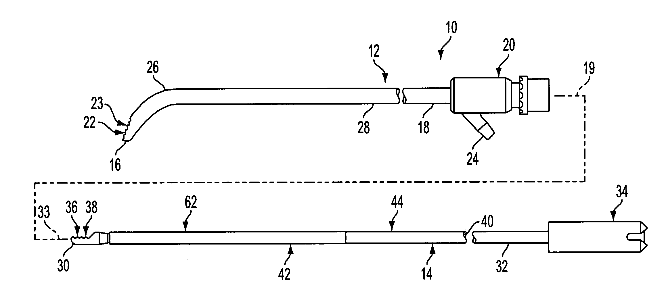
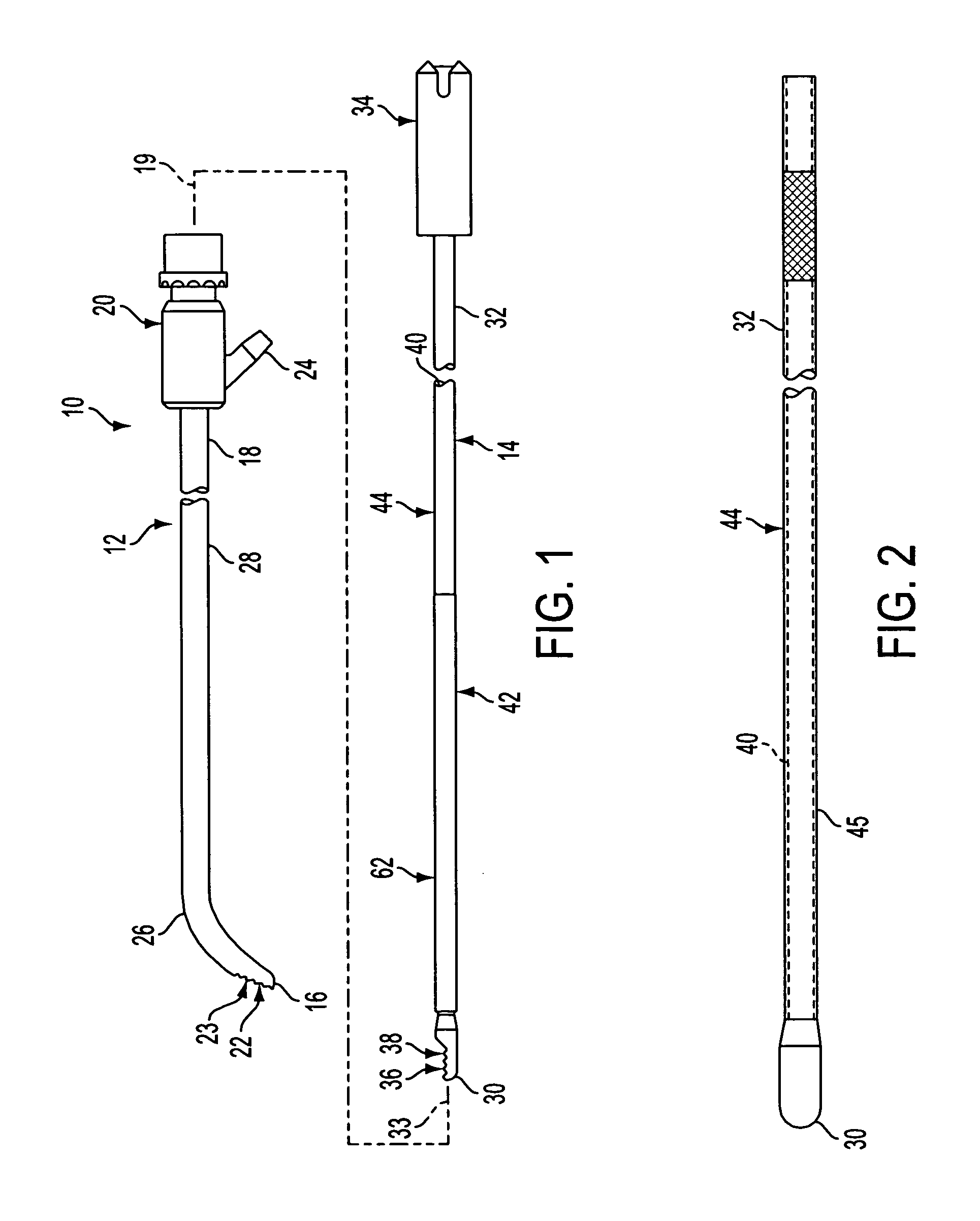
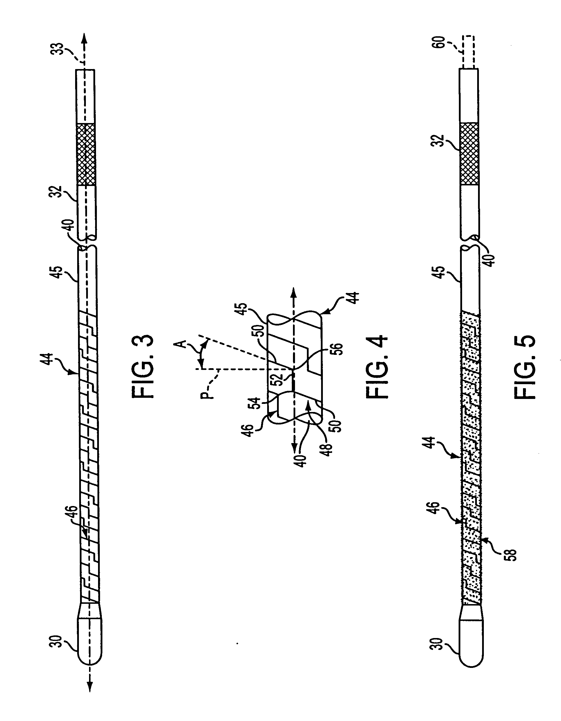
[0042] An angled tissue cutting instrument 10 according to the present invention is illustrated in FIG. 1 and comprises an elongate angled outer tubular member 12 and an elongate flexible inner tubular member 14 for being rotatably disposed in angled outer tubular member 12. The angled outer tubular member 12 is typically made of stainless steel and includes a distal end 16, a proximal end 18 and a central longitudinal axis 19 that follows a non-straight or angled longitudinal path. The proximal end 18 is typically attached to an outer member hub 20, which may be made of plastic. An opening is formed in the distal end 16 and defines a cutting port or window 22 providing communication with the lumen of the outer tubular member 12 from externally of distal end 16. The cutting port 22 can have various configurations and may be circumscribed by a peripheral edge. The peripheral edge that circumscribes the cutting port 22 can be a non-cutting edge or a cutting edge as depicted for outer ...


PUM


Abstract

An angled tissue cutting instrument comprises an angled outer tubular member rotatably receiving a flexible inner tubular member. The inner member has a flexible region in correspondence with an angle of the outer member. The flexible region comprises a helically cut length portion of an elongate tubular body of the inner member and a continuous solid flexible surface secured to an outer surface of the body along the helically cut length portion. A method of fabricating a flexible inner tubular member involves forming a helical cut through the solid wall of a length portion of a tubular body and securing a continuous solid flexible surface to the outer surface of the body along the helically cut length portion to form a flexible region.

Description

BACKGROUND OF THE INVENTION [0001] 1. Field of the Invention [0002] The present invention relates generally to tissue cutting instruments having an elongate inner member rotatably disposed in an elongate outer tubular member to cut anatomical tissue and, more particularly, to angled tissue cutting instruments and methods of fabricating angled tissue cutting instruments having an elongate flexible inner tubular member rotatably disposed in an elongate angled outer tubular member. [0003] 2. Discussion of the Related Art [0004] Surgical cutting instruments in which an elongate inner member is rotated within an elongate outer tubular member have become well accepted in surgical procedures where access to a cutting site in a patient's body is gained via a narrow or small size natural or surgically created anatomical opening or passage establishing communication with the cutting site from externally of the patient's body. Typically, the outer tubular member includes a distal end with an o...

Claims


Application Information

Patent Timeline
Patent Type & Authority Applications(United States)
IPC IPC(8): A61B17/28A61B17/32A61M1/00
CPCA61B17/32002A61B2017/00309A61B2217/007A61B2017/320032A61B2217/005A61B2017/2905
Inventor ADAMS, KENNETH M.
Owner MEDTRONIC XOMED INC
Why Eureka
Try Eureka