Image layout device

a technology of image layout and layout device, which is applied in the direction of static indicating device, instrument, editing/combining figures or text, etc., can solve the problems of time-consuming processing, unsatisfactory work of attaching photographs developed on conventional photographic paper to albums made of paper, and complicated calculation processing. , to achieve the effect of simple calculation processing, optimal distribution and high efficiency

Inactive Publication Date: 2005-04-28
SEIKO EPSON CORP
View PDF1 Cites 65 Cited by
  • Summary
  • Abstract
  • Description
  • Claims
  • Application Information

AI Technical Summary

Benefits of technology

[0011] An object of the invention to provide an image layout device and method that, by using a simple calculation processing and at a high efficiency, can automatically lay out a plurality of electronic images such as electronic photographs in a predetermined area.
[0012] The invention can be a device that automatically lays out a plurality of images within a particular area, and includes a layout angle determining device that determines the layout angle for each of the images based on an angle that is an integer multiple of a golden angle and a layout position determining device that determines the layout position for each of the images depending on the overlap between each of the images due to the angle determined by the layout angle determining device. Here, a golden angle is an angle in which the 360° circumference is divided by a golden ratio of 1:(1+{square root}5 / 2, and found by 360° / (1+(1+{square root}5) / 2)=137.507764. The golden ratio is known as the one that expresses the aspect ratio of the most balanced and beautiful rectangle. The golden angle is known, for example, to make small the overlap of leaves by leaves sprouting from the branch according to the golden angle in the arrangement of leaves, and makes possible the optimal distribution of sun light and rain. The invention determines the layout angle for each of the images based on an angle that is an integer multiple of a golden angle and determines the layout position for each of the images depending on the overlap between each of the images due to this determined angle. Therefore, it is possible to determine the layout position for each of the images by using a simple computing process. Furthermore, it is possible to obtain an efficient layout because the overlap between each of the images is small.
[0013] The invention can be a device that automatically lays out a plurality of images within a particular area, and includes a layout angle center position determining device that determines the center position of a layout angle at an arbitrary position within the area, a layout angle determining device that determines the layout angle for each of the images based on an angle that is an integer multiple of a golden angle, where the layout angle center position determined by the layout angle center position determining device serves as a reference, and a layout position determining device that determines the layout position for each of the images depending on the overlap between each of the images due to the angle determined by the layout angle determining device. Thereby, the center position of the layout angle can be arbitrarily set by the layout angle center position determining device, the layout angle for each of the angles can be set based on an angle that is an integer multiple of a golden angle that serves as a reference therefore, and the layout position for each of the images is determined according to the overlap with other images by the layout position determining device. Therefore, based on a predetermined layout angle, it is possible to determine a position for each of the images simply by laying out the new image is sequence such that the overlap with the arranged images is made small or eliminated, and it is possible to determine the layout position for each of the images efficiently by using simple calculation processing.
[0014] Specifically, the present invention determines the center position of the layout angle at an arbitrary position within an area, determines the layout angle for each of the images based on an angle that is an integer multiple of a golden angle, where this layout angle center position serves as a reference, and sets the layout position for each of the images based on the overlap between each of the images due to this determined angle. Therefore, it is possible to determine the layout position for each of the images by using a simple calculation processing. Furthermore, the present invention can obtain an efficient image layout because the overlap between each of the images can be made small easily.
[0015] The invention can be a device that automatically lays out a plurality of electronic images within a predetermined area, and includes a layout angle determining device that determines the layout angle for each of the images based on an angle that is an integer multiple of a golden angle; a layout position determining device that determines the layout position for each of the images according to the overlap between each of the images due to the angle determined by the layout angle determining device; and a layout angle revising device that revises the value of the integer of the predetermined angel that the layout angle determining device uses as a reference in the case that there are images whose layout position within a particular area could not be determined by the layout position determining device. Thus, the invention determines the layout angle for each of the images based on an angle that is an integer multiple of a golden angle, and determines the layout position for each of the images depending on the overlap between each of the images due to this determined angle. Therefore, it is possible to determine the layout position of each of the images by using a simple calculation processing. In addition, because the layout angle revising device revises the value of the integer multiple of the golden angle that the layout angle determining device uses as a reference in the case that there are images whose layout position within a particular area could not be determined, it is possible to make the number of images that can be laid out in the particular area large. In addition, because the overlap between each of the images can be easily made small, it is possible to obtain an efficient layout. Furthermore, it is possible to generate various layout pattern even for the same number of images.
[0016] The invention can be a device that automatically lays out a plurality of electronic images within a particular area, and includes a layout angle determining device that sets the center position that serves as a reference for the layout angle and determines the angle of the layout position for each of the images based on an angle that is an integer multiple of a golden angle, a layout reference area determining device that determines a layout reference area in which images can be laid out within a particular area, a layout position determining device that determines the layout position for each of the images depending on the overlap between each of the images due to the angle determined in the layout angle determining device and the layout reference area determined by the layout reference area determining device, and a layout angle revising device that revises the value of the integer multiple of the golden angle that the layout angle determining device uses as a reference in the case that there are images whose layout position could not be determined by the layout position determining device. Thereby, the present invention can determine the position of each of the images simply by laying out new images in sequence such that the overlap between already laid out images is made small or eliminated; and it is possible to determine efficiently the layout position for each of the images by using simple computation processes. Therefore, according to the present invention, it is possible to determine the layout position for each of the images by using a simple computation processing and furthermore make the overlap between each of the images small, and thus it is possible to obtain an efficient layout.

Problems solved by technology

Thus, in photograph albums, the tedious work of attaching photographs developed on conventional photographic paper to albums made of paper has become undesirable.
In this case, in this method, when the layout of the template is unsatisfactory, the only other option is to choose another template.
However, in the case of this related technology, although the layout of the images is determined automatically, complicated calculation processing is required.
Thus, there are the problems that the processing requires time and a high capacity computer is necessary.
In addition, in the case of other related examples, although layout of the images is determined automatically, there can be no guarantee that the layout obtained as a result thereof will one that is satisfying to the user.

Method used


Image

  • Image layout device
  • Image layout device
  • Image layout device

Examples


first exemplary embodiment

[0036] Below, a first embodiment of the invention will be explained with reference to the figures.

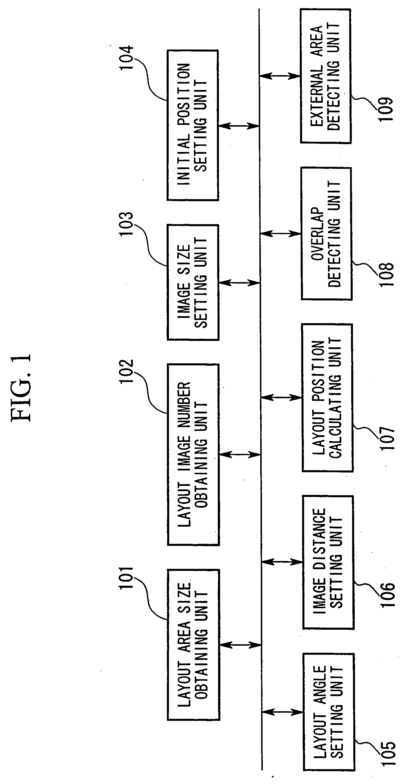
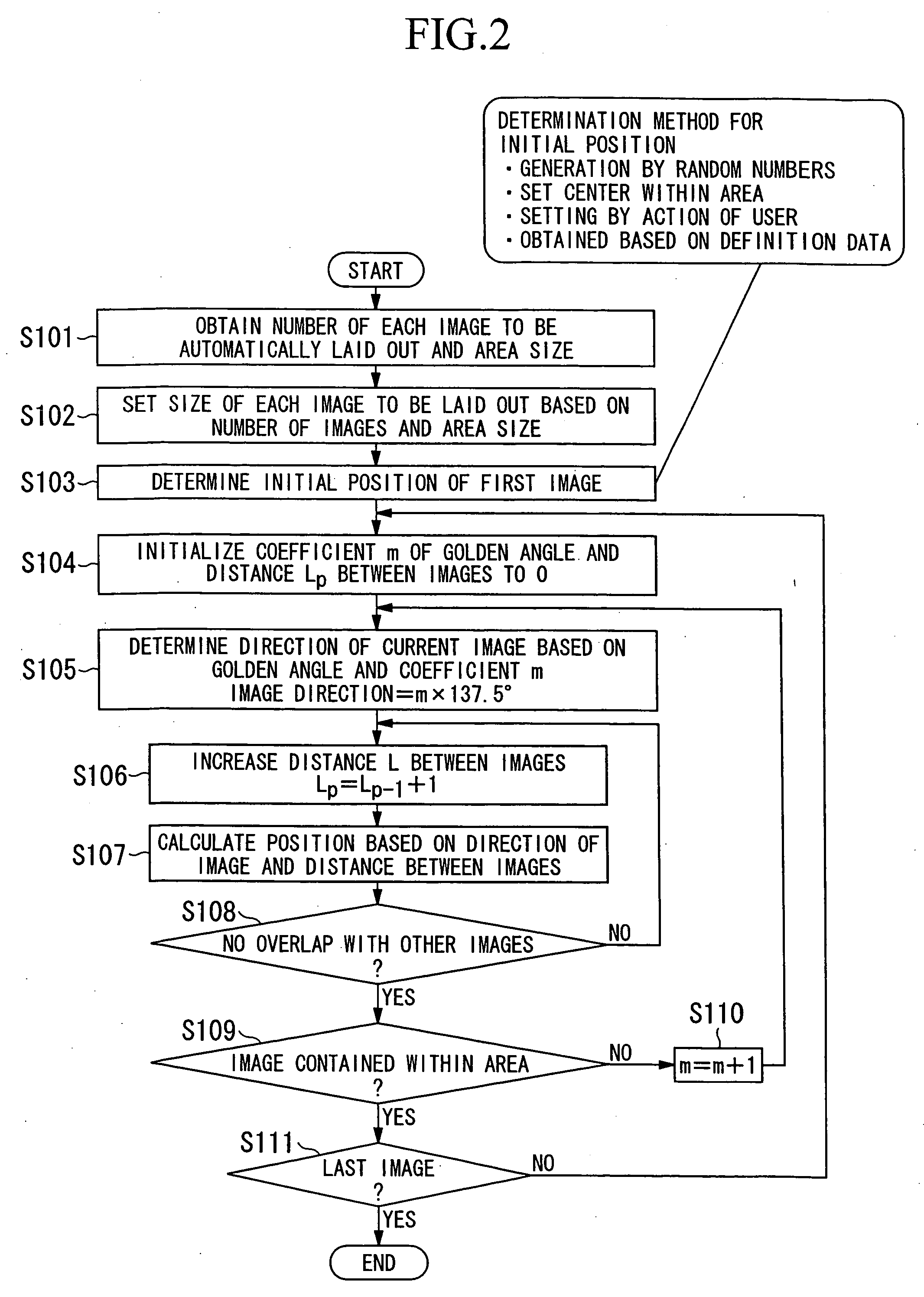
[0037]FIG. 1 is a block diagram for explaining the structure of the image layout device of the present invention. FIG. 2 is a flowchart for explaining an example of the operation thereof. The image layout device of the present embodiment is structured by a general use computer that provides a central processing unit, a memory device, keyboard, mouse, display device, a memory device that uses a optical recording medium or the like; peripheral devices such as a printer, digital camera and the like; and a program for image layout processing that is executed on a predetermined system software by a computer. FIG. 1 shows each of the functions of the image layout processing program divided into blocks.

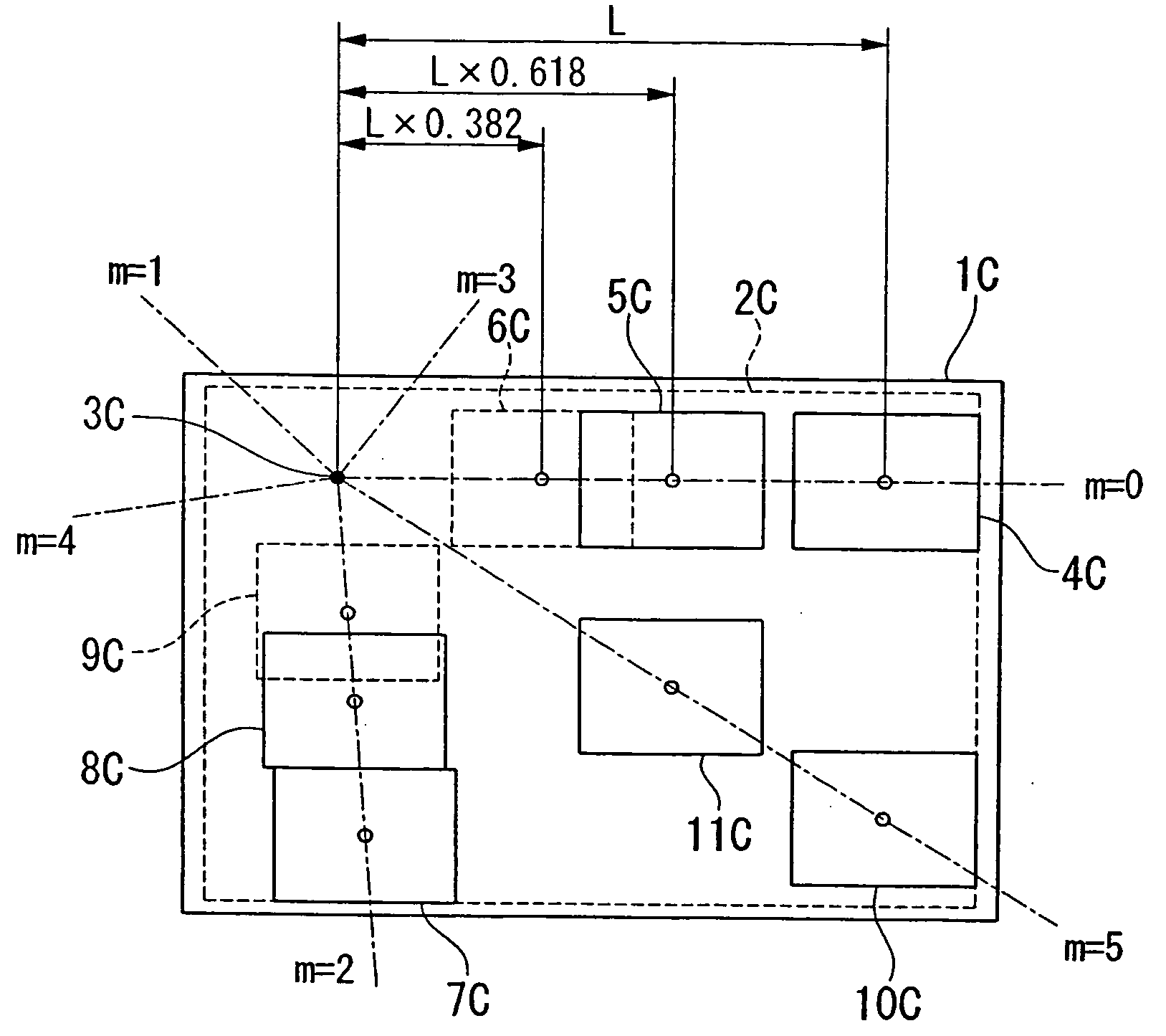
[0038] In FIG. 1 and FIG. 2, an image layout device (image layout program) that is started up due to an operation by the user (operator) obtains the area size in which the images will be laid ...

second exemplary embodiment

[0076] Below, a second embodiment of the invention will be explained with reference to the drawings.

[0077]FIG. 5 is a block diagram for explaining the structure of the image layout device of the present invention. FIG. 6 is a flowchart for explaining an example of the operation thereof. The image layout device of the present embodiment is structured by a general use computer that provides a central processing unit, a memory device, keyboard, mouse, display device, a memory device that uses a optical recording medium or the like; peripheral devices such as a printer, digital camera and the like; and a program for image layout processing that is executed on predetermined system software by a computer. FIG. 5 shows each of the functions of the image layout processing program divided into blocks.

[0078] In FIG. 5 and FIG. 6, an image layout device (image layout program) that is started up due to an operation by the user (operator) obtains an area size for laying out the images that the...

third exemplary embodiment

[0109] Below, a third embodiment of the present invention will be explained with reference to the figures.

[0110]FIG. 9 is a block diagram for explaining the structure of the image layout device of the present invention. FIG. 10 is a flowchart for explaining an example of the operation thereof. The image layout device of the present embodiment is structured by a general use computer that provides a central processing unit, a memory device, keyboard, mouse, display device, a memory device that uses a optical recording medium or the like; peripheral devices, such as a printer, digital camera and the like; and a program for image layout processing that is executed on a predetermined system software by a computer. FIG. 9 shows each of the functions of the image layout processing program divided into blocks.

[0111] In FIG. 9 and FIG. 10, an image layout device (image layout program) that is started up due to an operation by the user (operator) obtains an area size for laying out the imag...


PUM


Abstract

Aspects of the invention can relate to an image layout device and an image layout method. The image layout device of the invention can be a device that automatically arranges a plurality of images within a particular area, and can include a layout angle determining device that determines the layout angle for each of the images based on an angle that is an integer multiple of a golden angle, and a layout position determining device that determines the layout position for each of the images depending on the overlap between each of the images due to the angle determined by the layout angle determining device.

Description

RELATED APPLICATIONS [0001] The present application is based on and claims priority to Japanese patent application Nos. 2003-306810, 2004-022294, and 2004-029496, and 2004-173948 filed in Japan, the content of which is incorporated herein by reference in its entirety. BACKGROUND OF THE INVENTION [0002] 1. Field of Invention [0003] Aspects of the invention can relate to an advantageous image layout device and method used when automatically determining the layout of a plurality of images to a predetermined region. [0004] 2. Description of Related Art [0005] The use of electronics in photography is steadily progressing due to the spread of digital cameras and camera equipped cell phones. Thus, in photograph albums, the tedious work of attaching photographs developed on conventional photographic paper to albums made of paper has become undesirable. That is, many users lay out electronic pictures in an electronic photograph album that is realized by using, for example, a computer and sof...

Claims


Application Information

Patent Timeline
Patent Type & Authority Applications(United States)
IPC IPC(8): G06F3/033G06F3/048G06F17/21G06T11/60
CPCG06F3/0481G06T11/60G06F17/211G06F40/103
Inventor YAMAKADO, HITOSHIGU, YUMIYAMOTO, TORU
Owner SEIKO EPSON CORP
Why Eureka
Try Eureka