Negative pressure type booster

a negative pressure type and booster technology, applied in the direction of braking systems, vehicle components, servomotors, etc., can solve the problems of reducing the accuracy of disengagement timing, the vehicle fails to exhibit sufficient braking capability, and the tendency toward a variation in the threshold value, so as to reduce the number of components and reduce the negative pressure type booster

Inactive Publication Date: 2005-05-05
ADVICS CO LTD
View PDF5 Cites 6 Cited by
  • Summary
  • Abstract
  • Description
  • Claims
  • Application Information

AI Technical Summary

Benefits of technology

[0013] The negative pressure type booster of the present invention may be configured in such a manner that a single latch member is disposed in the power piston. In this case, a single radially extending hole for receiving the latch member is formed in the power piston. Thus, the power piston can assume sufficiently high strength. Also, the number of component parts of the negative pressure type booster can be reduced, whereby the negative pressure type booster can have a simple configuration.
[0014] The negative pressure type booster of the present invention may be configured in such a manner that the latch member is mounted in a radially extending hole formed in the power piston, in such a manner as to be linearly movable in a radial direction, and can project radially outward from the power piston; and the biasing member for biasing the latch member radially inward is a ringlike elastic member that is attached to the outer circumference of the power piston. In this case, the latch member and the biasing member can be mounted from the outside of the power pisto

Problems solved by technology

Recent analyses have revealed that, in many cases, a vehicle fails to exhibit its braking capability sufficiently when a driver steps on a brake pedal in alarm upon sudden emergence of an obstacle in the path of the vehicle; i.e., during emergency braking, since a force that the driver applies to a brake pedal is considerably s

Method used


Image

  • Negative pressure type booster
  • Negative pressure type booster
  • Negative pressure type booster

Examples


Embodiment Construction

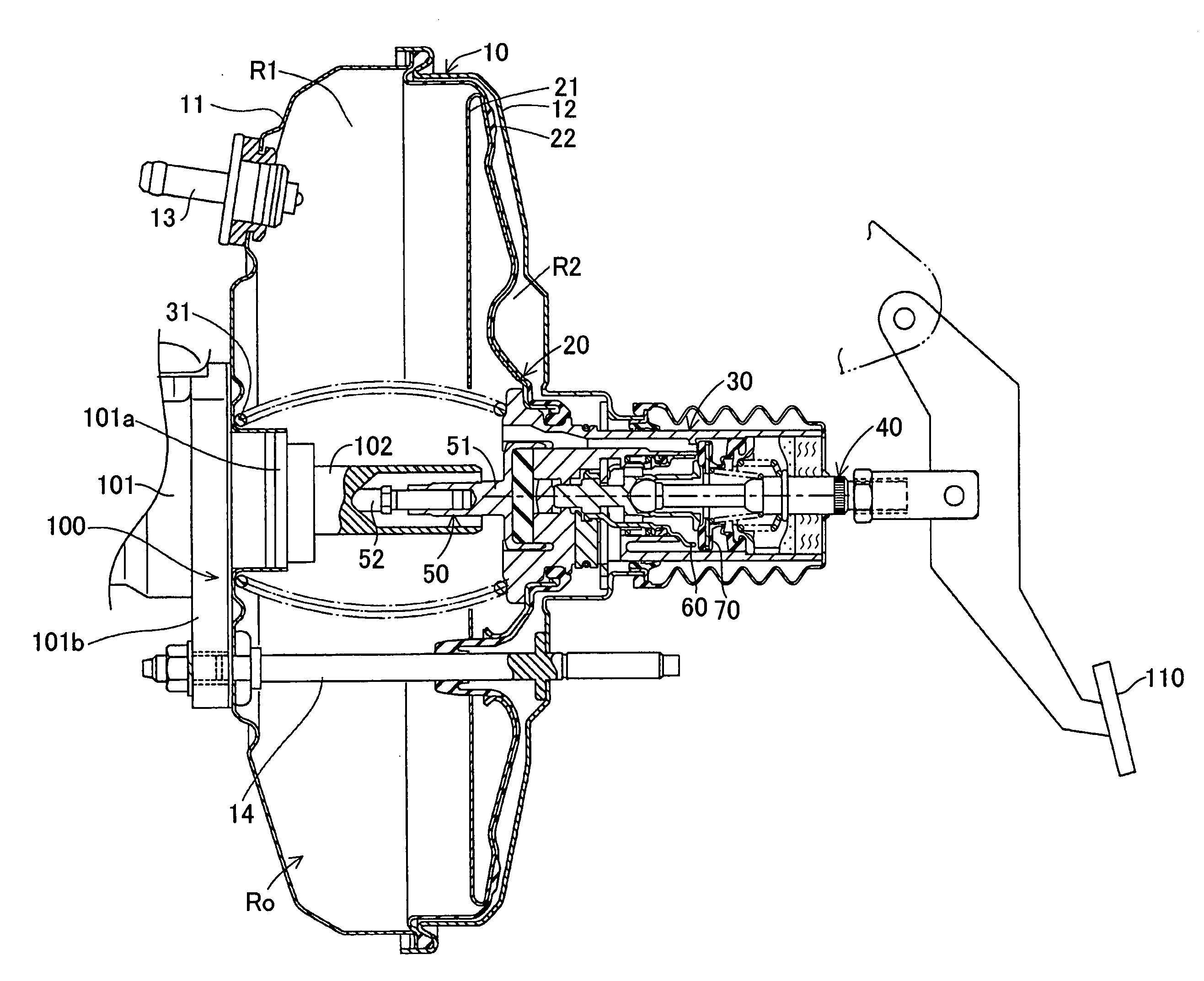
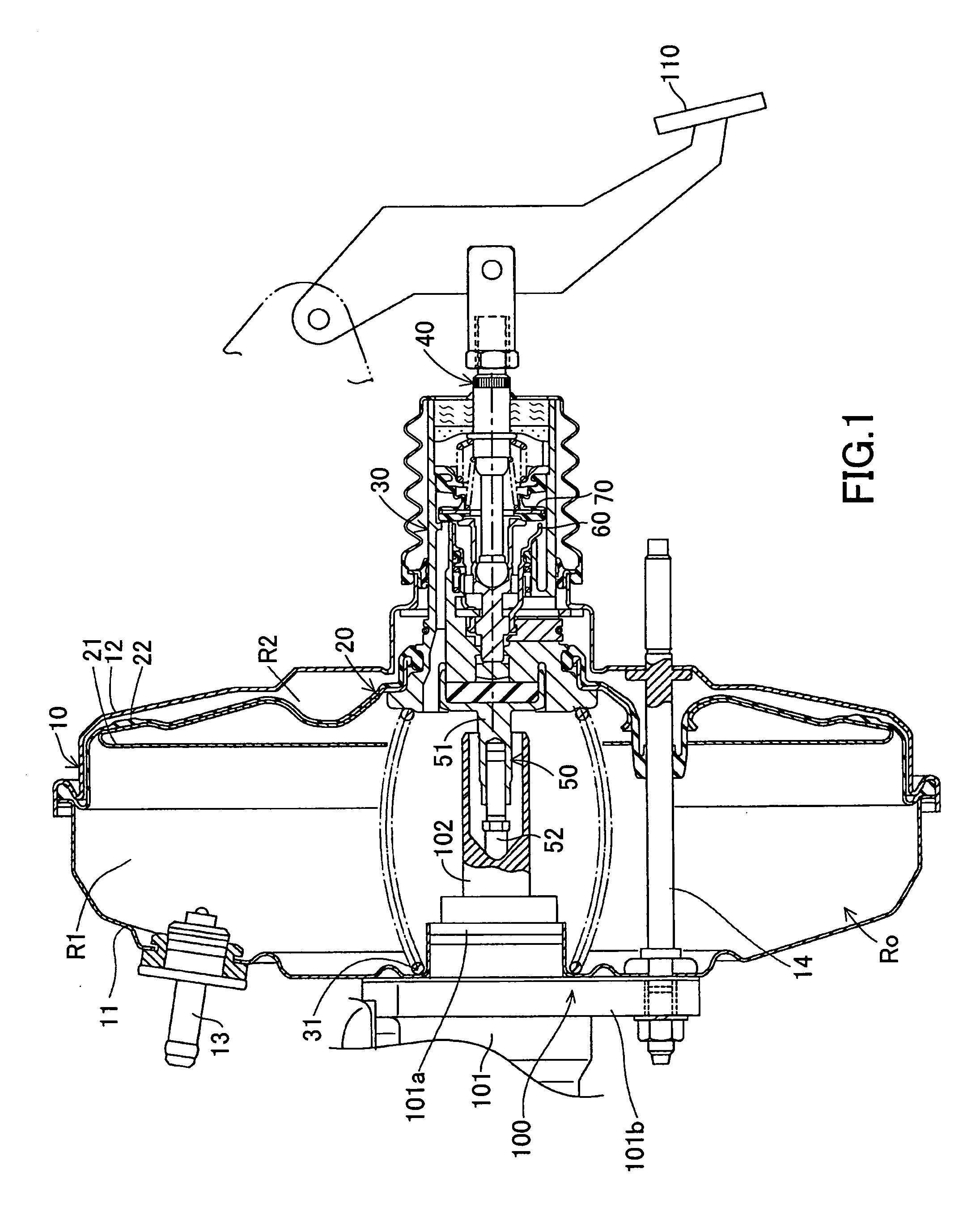
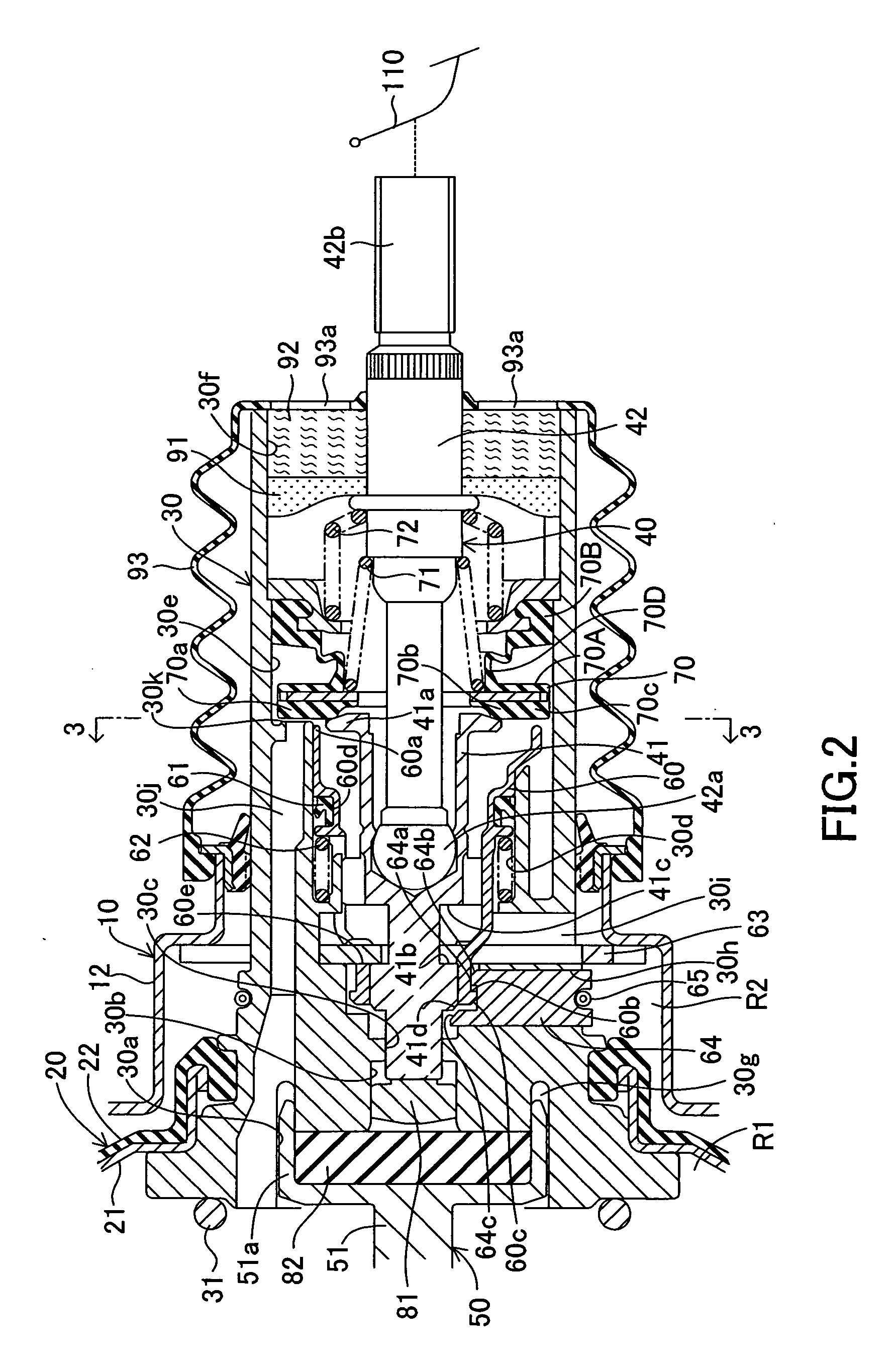
[0026] An embodiment of the present invention will next be described in detail with reference to the drawings. FIGS. 1 to 3 show a negative pressure type booster according to the present embodiment. The negative pressure type booster includes a movable diaphragm 20 and a power piston 30, which are mounted to a housing 10, as well as an input member 40, an output member 50, a slide valve 60, and a control valve 70, which are mounted in the power piston 30.

[0027] As shown in FIG. 1, the housing 10 includes a front shell 11 and a rear shell 12. The front and rear shells 11 and 12 define a pressure chamber Ro therein. The movable diaphragm 20 divides the pressure chamber Ro into a constant-pressure chamber R1 and a variable-pressure chamber R2. The constant-pressure chamber R1 communicates with a vacuum source (e.g., an unillustrated intake manifold of an engine) at all times via a vacuum introduction pipe 13. Communication is established / shut off between the variable-pressure chamber ...


PUM


Abstract

A negative pressure type booster includes a power piston, a slide valve, and a holding mechanism, among others, and assists a driver during emergency braking. The holding mechanism is adapted to hold the slide valve at a predetermined frontward position, and includes a latch member that is mounted to the power piston in such a manner as to be linearly movable in a radial direction, and a garter spring for biasing the latch member radially inward. The latch member has a hook that can be engaged with and disengaged from a hook provided on the slide valve. When a plunger moves frontward relative to the power piston by a quantity greater than a predetermined value, a push slope provided on the plunger pushes a passive slope provided on the latch member radially outward, whereby the hook of the latch member is disengaged from the hook of the slide valve.

Description

BACKGROUND OF THE INVENTION [0001] 1. Field of the Invention [0002] The present invention relates to a negative pressure type booster for use in a vehicular brake system, and more particularly to a negative pressure type booster for making up for lack of force at a brake pedal so as to assist a driver during emergency braking. [0003] 2. Description of the Related Art [0004] Recent analyses have revealed that, in many cases, a vehicle fails to exhibit its braking capability sufficiently when a driver steps on a brake pedal in alarm upon sudden emergence of an obstacle in the path of the vehicle; i.e., during emergency braking, since a force that the driver applies to a brake pedal is considerably smaller than a force that generates such a high brake fluid pressure as to cause wheel lock-up. On the basis of the analytic results, there have been proposed and put into practical use devices that judge from the speed of stepping on a brake pedal or the rate of increase of the fluid pressu...

Claims


Application Information

Patent Timeline
IPC IPC(8): B60T8/32B60T13/57B60T13/52B60T13/575B60T13/577
CPCB60T8/3275B60T13/577B60T13/575B60T13/52
Inventor TSUBOUCHI, KAORUINOUE, YOJISAKAI, TOMOYASUTAKATORI, YOKO
Owner ADVICS CO LTD
Why Eureka
Try Eureka