Hot air furnace

a furnace and hot air technology, applied in the field of furnaces, can solve the problems of reducing affecting the efficiency of the furnace,

Inactive Publication Date: 2005-05-05
SCHONBERGER SR MARTY L
View PDF24 Cites 35 Cited by
  • Summary
  • Abstract
  • Description
  • Claims
  • Application Information

AI Technical Summary

Benefits of technology

[0015] In the illustrated embodiment, a structure defining a flame target and gas diffuser is located inside of the combustion chamber. It is preferred that the structure be constructed of ceramic and is cup-like in construction. An open end of the cup is oriented towards the burner. The end face of the cup is located adjacent an outlet of the combustion chamber which communicates with the transfer channel. The target/diffuser serves two functions. Firstly, it forces the products of combustion to...

Problems solved by technology

This heat loss substantially reduces the efficiency of the furnace.
However, it has been found that under certain operating conditions, some instability in the burning process may occur.
This...

Method used


Image

  • Hot air furnace
  • Hot air furnace
  • Hot air furnace

Examples


Embodiment Construction

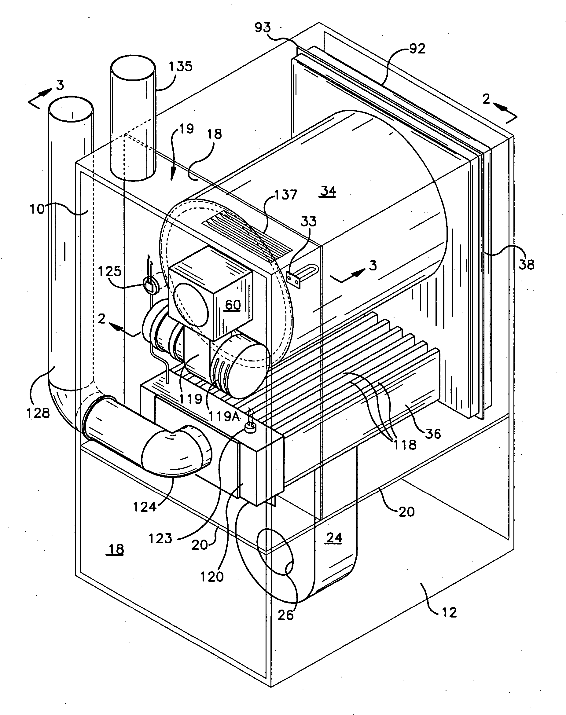
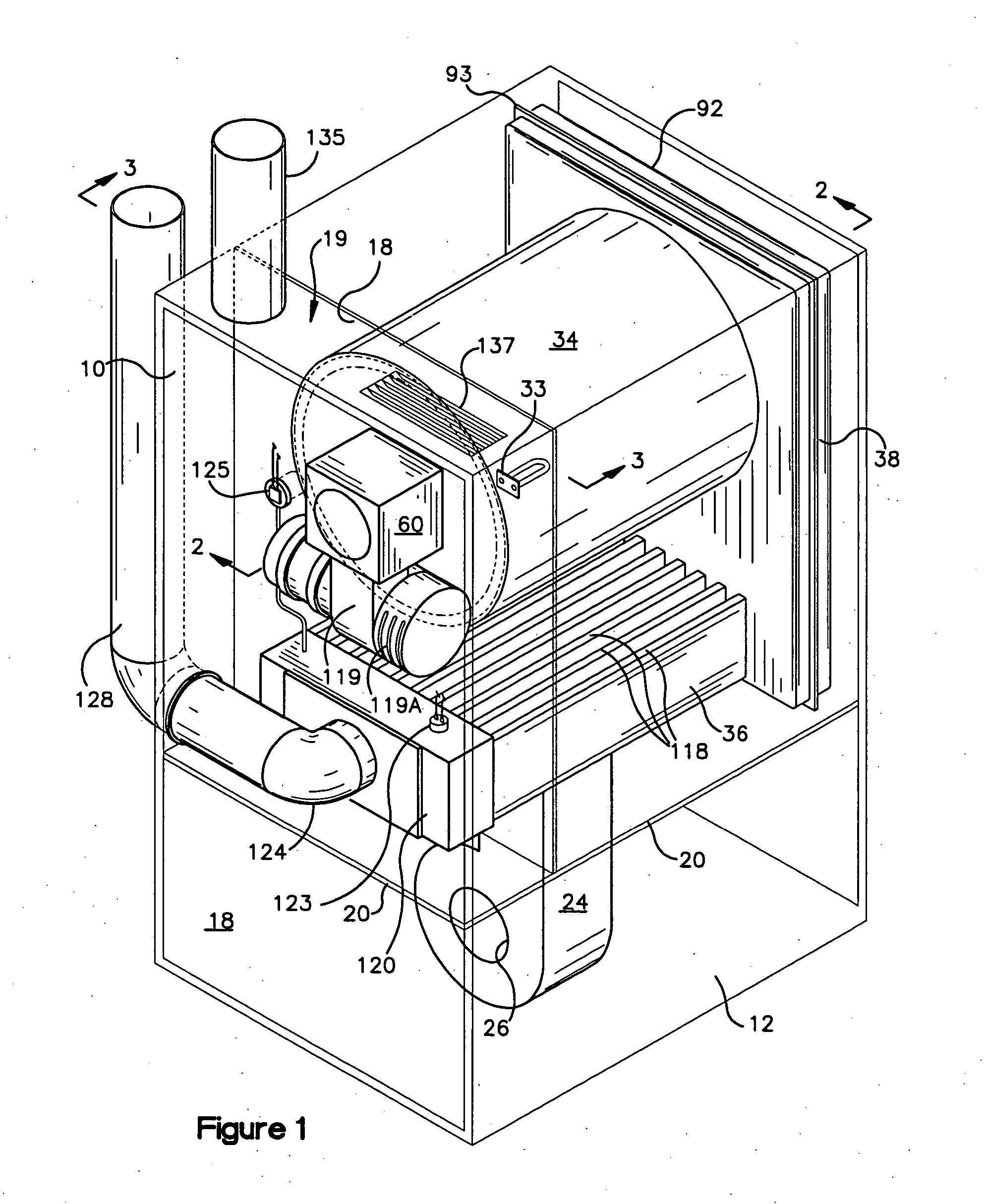
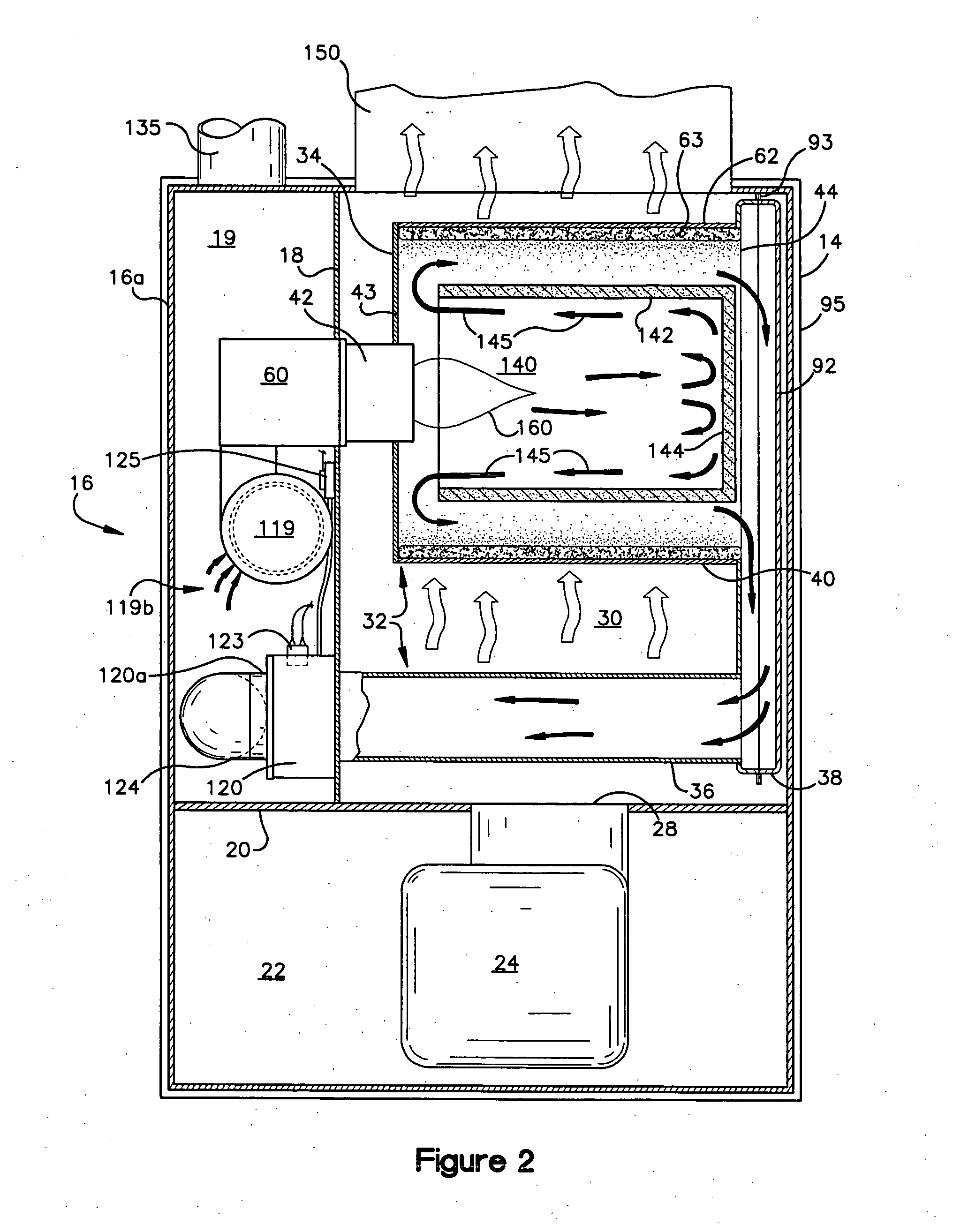
[0022]FIGS. 1-3 illustrate the overall construction of a hot air furnace embodying the present invention. Referring first to FIGS. 1 and 2, the furnace includes frame structure defined in part by side walls 10, 12 and rear wall 14. The front of the furnace indicated generally by the reference character 16 in FIG. 2 is enclosed by a removable front wall 16a which may be in the form of an access door (not shown), as is conventional. An intermediate panel 18 is positioned inwardly with respect to the outer front wall 16a or door (not shown) of the furnace and extends between the side walls 10, 12. The intermediate panel 18, the front wall 16a and the portions of the sidewalls 10, 12 between the panel 18 and front wall 16a together define a combustion air inlet chamber 19 (shown best in FIG. 2).

[0023] A transverse support self 20 is mounted a predetermined distance above the base of the furnace. A comfort air input chamber 22 Which houses a conventional furnace blower 24 having an axia...


PUM


Abstract

Disclosed is a high efficiency hot air furnace including a heat exchanger assembly located in a heat exchange chamber through with comfort air is passed to be heated. The heat exchanger assembly includes a drum like combustion member located in the flow path of comfort air. A supplemental heat exchanger or condenser is disposed in the flow path of comfort air upstream from the combustion member. A transfer channel extends from one end of the combustion member and communicates combustion products to the condenser. The combustion member includes an insulating material on the inside portion of the cylindrical wall. A diffuser is located within the combustion member which prevents the burner flame from extending into the transfer channel. The burner includes a blower for urging combustion gases through the heat exchanging assembly. Intake air for the blower is provided by an air intake chamber.

Description

CLAIM FOR PRIORITY [0001] The present application is a non-provisional application claiming priority from U.S. Provisional Application Ser. No. 60 / 517,262 filed on Nov. 3, 2003, entitled HOT AIR FURNACE.FIELD OF THE INVENTION [0002] The present invention relates generally to furnaces and in particular to an oil fired, condensing mode hot air furnace. BACKGROUND [0003] Conventional hot air furnaces used in residential and commercial buildings generally include a fuel burner which burns oil, gas or other suitable fuel. The burner heats a heat exchanger which is positioned in a flow path of air to be heated (often termed “comfort air”). Heat from the combustion chamber is transferred to the air and the air is then distributed throughout the building. [0004] Many prior art furnaces include rather large heat exchangers in order to maximize the heat extracted from the combustion of fuel. The more efficiency desired, the larger the heat exchanger must be. Alternately, supplementary heat ex...

Claims


Application Information

Patent Timeline
IPC IPC(8): F23M9/06F24H3/02F24H3/10F24H8/00F25D3/02
CPCF23M9/06Y02B30/102F24H8/00F24H3/105Y02B30/00
Inventor SCHONBERGER, MARTY L. SR.
Owner SCHONBERGER SR MARTY L
Why Eureka
Try Eureka