Turbulent flow and rotational flow negative pressure drying machine

A negative pressure drying and turbulent flow technology, applied in the direction of dryers, drying solid materials, drying gas arrangement, etc., can solve the problems of dust particles overflowing, disturbing residents, increasing energy consumption and cost of processing, etc., to achieve heating degree and The degree of pulverization, sufficient pulverization, and high drying efficiency

Pending Publication Date: 2018-05-04
深圳市泽源能源股份有限公司
View PDF8 Cites 2 Cited by
  • Summary
  • Abstract
  • Description
  • Claims
  • Application Information

AI Technical Summary

Problems solved by technology

[0002] In the field of drying, wet materials are mainly dried by hot cyclones. When encountering some materials that are difficult to dehydrate, such as: heat-sensitive sludge containing biological intracellular water, there are mainly the following problems when drying with existing drying equipment: 1) A large amount of water is stored in the cells, and the existing drying technology basically fails to remove the water fundamentally, and it is difficult to achieve the drying effect; 2) Due to the heat sensitivity of the material, it cannot be evaporated simply by increasing the drying temperature This moisture has been a technical problem that has plagued relevant practitioners; 3) In the process of drying materials in common drying equipment, due to the high internal pressure, there is often odor emission and dust particles overflowing, not only difficult to meet environmental protection indicators, but also The phenomenon of disturbing the residents is serious; 4) In order to reduce the final moisture content of the material as much as possible, the existing drying technology will make the drying process long enough, which also increases the energy consumption and cost of the treatment

Method used


Image

  • Turbulent flow and rotational flow negative pressure drying machine
  • Turbulent flow and rotational flow negative pressure drying machine
  • Turbulent flow and rotational flow negative pressure drying machine

Examples


Embodiment Construction

[0025] The present invention will be further described in detail below in conjunction with the accompanying drawings to facilitate a clearer understanding of the present invention, but they do not limit the present invention.

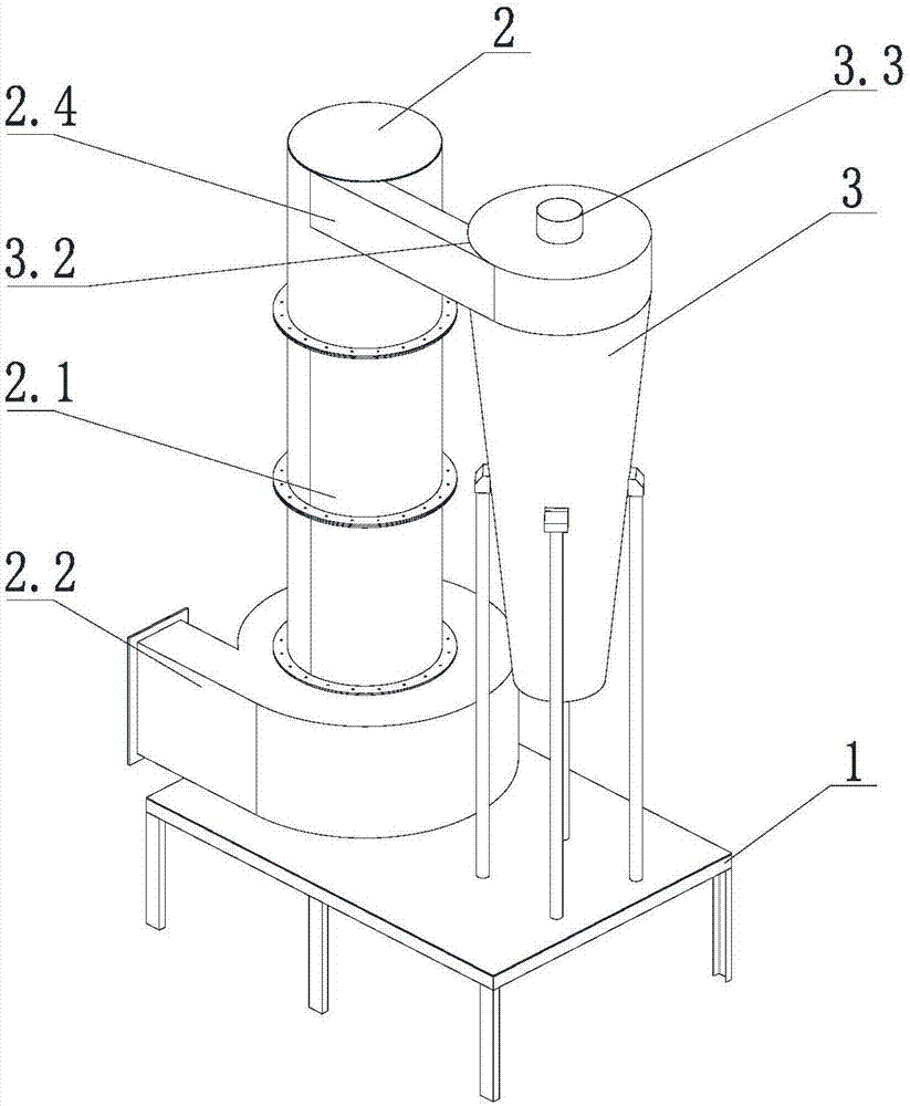
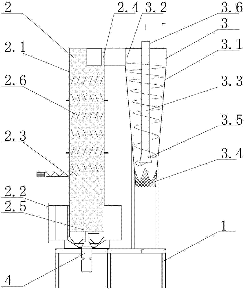
[0026] figure 1 , figure 2 The shown turbulent flow negative pressure dryer includes a machine base 1, on which a connected turbulent section 2 and a swirl section 3 are fixed, the turbulent section 2 includes a cavity 2.1, and the cavity 2.1 is a hollow circle Cylindrical, with airtight top and bottom surfaces, multiple rows of baffle arrays 2.6 for enhancing turbulent flow are arranged on the upper part of the inner wall of the cavity 2.1, a hot air inlet 2.2 is installed at the bottom of the cavity 2.1, and a humid material inlet 2.3 is arranged above the hot air inlet 2.2 , the upper end of the chamber 2.1 is provided with a hot air outlet 2.4, and the inner bottom of the chamber 2.1 is provided with a cutter 2.5 which is driven by a motor and can...


PUM


Abstract

The invention discloses a turbulent flow and rotational flow negative pressure drying machine which comprises a machine base. A turbulent flow section and a rotational flow section which communicate with each other are fixed to the machine base. The turbulent flow section comprises a cavity, and a hot-blast air inlet is formed in the bottom end of the cavity. A damp material inlet is formed abovethe hot-blast air inlet. A hot-blast air outlet is formed in the upper end of the cavity. A cutter capable of rotating at a high speed is arranged at the inner bottom of the cavity. The rotational flow section comprises an inverted cone cavity, and an air inlet connected with the hot-blast air outlet is formed in the top of the inverted cone cavity. An air outlet tube is connected into the inverted cone cavity. The turbulent flow and rotational flow negative pressure drying machine is good in drying effect and high in drying efficiency, and energy consumption is greatly reduced; and moreover,the whole system is clean, sanitary and free of stinks, and the drying problem of materials which cannot be dewatered easily is solved.

Description

technical field [0001] The invention relates to drying equipment, in particular to a turbulent-flow swirl negative-pressure dryer. Background technique [0002] In the field of drying, wet materials are mainly dried by hot cyclones. When encountering some materials that are difficult to dehydrate, such as: heat-sensitive sludge containing biological intracellular water, there are mainly the following problems when drying with existing drying equipment: 1) A large amount of water is stored in the cells, and the existing drying technology basically fails to remove the water fundamentally, and it is difficult to achieve the drying effect; 2) Due to the heat sensitivity of the material, it cannot be evaporated simply by increasing the drying temperature This moisture has been a technical problem that has plagued relevant practitioners; 3) In the process of drying materials in common drying equipment, due to the high internal pressure, there is often odor emission and dust partic...

Claims


Application Information

Patent Timeline
Patent Type & Authority Applications(China)
IPC IPC(8): F26B17/10F26B21/00F26B25/00
CPCF26B17/10F26B21/00F26B25/00
Inventor 陈沛波曾秀仪欧志明陈义龙张龙斌邬洪潮黄安虎王嘉颖
Owner 深圳市泽源能源股份有限公司
Why Eureka
Try Eureka