Method and apparatus for sealing and re-sealing an annular vessel opening

a technology for annular openings and sealing methods, applied in the field of sealing mechanisms, can solve the problems of many limitations related to use-ability and convenience in manufacturing, inability to adjust the seal strength, and mechanically dependent parts often bend or otherwise lose usefulness

Inactive Publication Date: 2005-05-05
CHANTALAT VINIT
View PDF18 Cites 15 Cited by
  • Summary
  • Abstract
  • Description
  • Claims
  • Application Information

AI Technical Summary

Benefits of technology

[0013] In some embodiments the retention housing is keyed to the threaded portion of the screw stem body using a key engaging a key slot in the body to prevent rotation of the housing about the body. Also in some embodiments the retention housing includes a retention cap and a gripping cup the gripping cup gripping the inner surface of the retention cap to prevent inter-rotation of the components.

Problems solved by technology

A drawback with this kind of device is that it is not adjustable in terms of seal strength and must be manufactured for a specific size bottle opening.
Many conventional stoppers are of the just-described type and have many limitations related to use-ability and convenience in manufacturing.
A limitation of this device is that it requires a bottle opening to have a lip to which the apparatus must be dimensionally adapted.
Moreover, such mechanically dependent parts often bend break or otherwise lose usefulness with improper or even repeated use.
The device has the same limitations as the lever actuated sealing device described further above with respect to fragile and obstructive moving parts and must be forcibly held down against the bottle before sealing can be affected.
Persuasively, the prior-art stoppers mentioned above are limited in application to specific implementations of consumer bottles of pre-known shapes, sizes and dimensions.

Method used


Image

  • Method and apparatus for sealing and re-sealing an annular vessel opening
  • Method and apparatus for sealing and re-sealing an annular vessel opening
  • Method and apparatus for sealing and re-sealing an annular vessel opening

Examples


Embodiment Construction

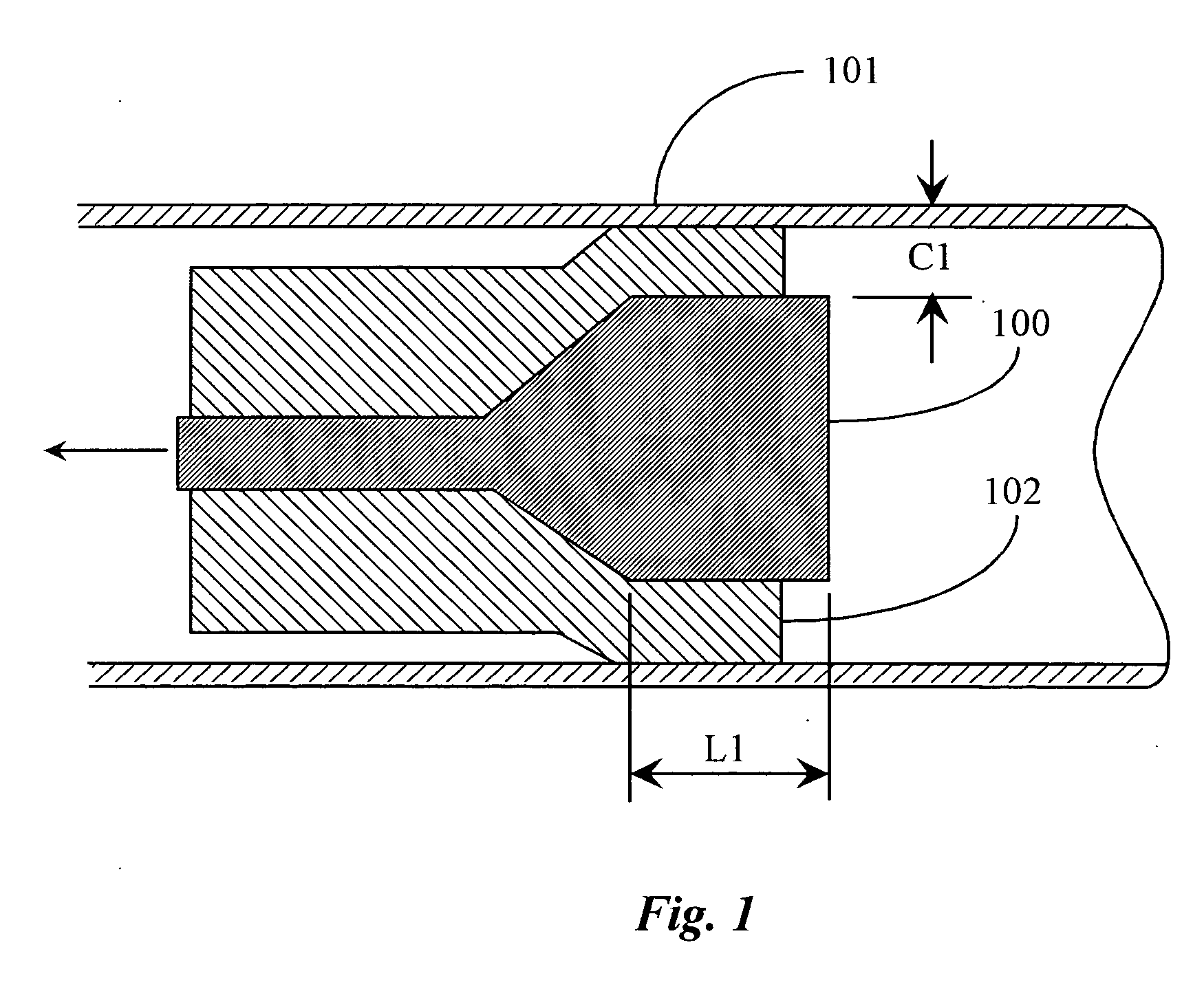
[0034]FIG. 1 is a block diagram illustrating a sealing principle applied by a device of the present invention in an annular opening of a vessel according to an embodiment of the present invention. As was described with respect to the background section of this specification, prior-art sealing methods for sealing an annular opening of a bottle or vessel are limited by mechanical frailty and stringent dimensional concerns. A device for sealing annular openings according to an embodiment of the present invention, also termed herein a stopper assembly by the inventor, uses a rubber sleeve or, in some variations, a rubber socket 102, to form a peripheral seal around the inner wall of a vessel opening 101, such as a bottle neck. To affect a strong seal, a principle of forced flare-out of the sleeve is practiced using an axially motivated tapered stem 100.

[0035] Sleeve 102 is an elastic rubber-like material that is pliable under force but reverts to its natural and original shape in the a...


PUM

PropertyMeasurementUnit
elasticaaaaaaaaaa
seal strengthaaaaaaaaaa
internal pressureaaaaaaaaaa

Abstract

A stopper assembly for sealing an opening of a vessel has a threaded body having a tapered head; an elastic jacket fitted over a portion of the body; a retention housing fitted over the body and jacket, the retention housing retaining the jacket from lateral displacement there through; and a turning nut attached to the retention housing and threaded to the body. A user inserts the stopper assembly into the vessel opening, holds the retention housing stable, and turns the turning nut causing travel of the threaded body through the retention housing and deformation of the elastic jacket against the tapered head, deformation thereof directed radially outward to make peripheral contact with the inner surface of the opening affecting a seal of the opening.

Description

CROSS-REFERENCE TO RELATED DOCUMENTS [0001] The present application is a continuation-in-part of pending application U.S. Ser. No. 10 / 697,061 filed Oct. 29, 2003, included herein in its entirety by reference.FIELD OF THE INVENTION [0002] The present invention is in the field of sealing mechanisms and pertains particularly to methods and apparatus for sealing and or re-sealing annular openings of containers, vessels, and delivery systems having nozzle-type annular openings. BACKGROUND OF THE INVENTION [0003] In the art of airtight sealing there are a variety of sealing mechanisms that are available for resealing a vessel opening, typically a bottle neck, that previously been opened. A very common example in the prior-art of record is re-sealing a Champaign bottle or other bottle type adapted to contain pressurized and non-pressurized liquids. [0004] The inventor is aware of a stopper device referenced herein by U.S. Pat. No. 3,937,350, which comprises a cap or hood, an elongated rubb...

Claims


Application Information

Patent Timeline
Patent Type & Authority Applications(United States)
IPC IPC(8): B01F3/04B65B31/04B65D39/12B65D51/16
CPCB01F3/04794B65D39/12B65B31/047B01F23/2361
Inventor CHANTALAT, VINIT
Owner CHANTALAT VINIT
Why Eureka
Try Eureka