Method for interconnecting tubulars by forge welding

Inactive Publication Date: 2005-05-05
SHELL OIL CO
View PDF20 Cites 10 Cited by
  • Summary
  • Abstract
  • Description
  • Claims
  • Application Information

AI Technical Summary

Benefits of technology

[0011] The use of three or more circumferentially spaced electrodes in the method and system according to the invention reduces unequal heating of the pipe e

Problems solved by technology

A disadvantage of using hydrogen as flushing gas is that it will react with oxygen in the atmosphere in an explosive fashion so that it

Method used


Image

  • Method for interconnecting tubulars by forge welding
  • Method for interconnecting tubulars by forge welding
  • Method for interconnecting tubulars by forge welding

Examples


Embodiment Construction

[0015] The invention will be described in more detail and by way of example with reference to the accompanying drawings in which:

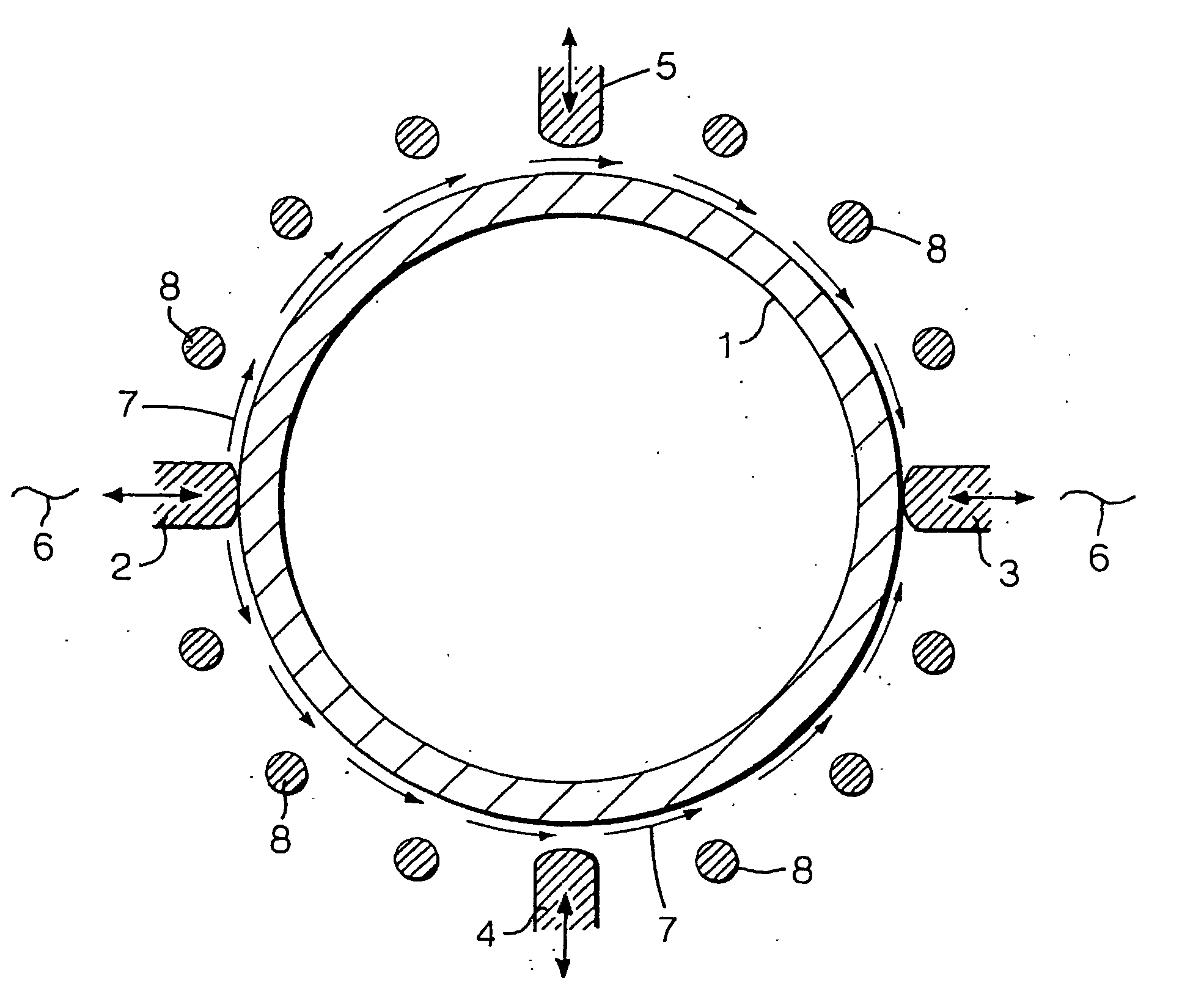
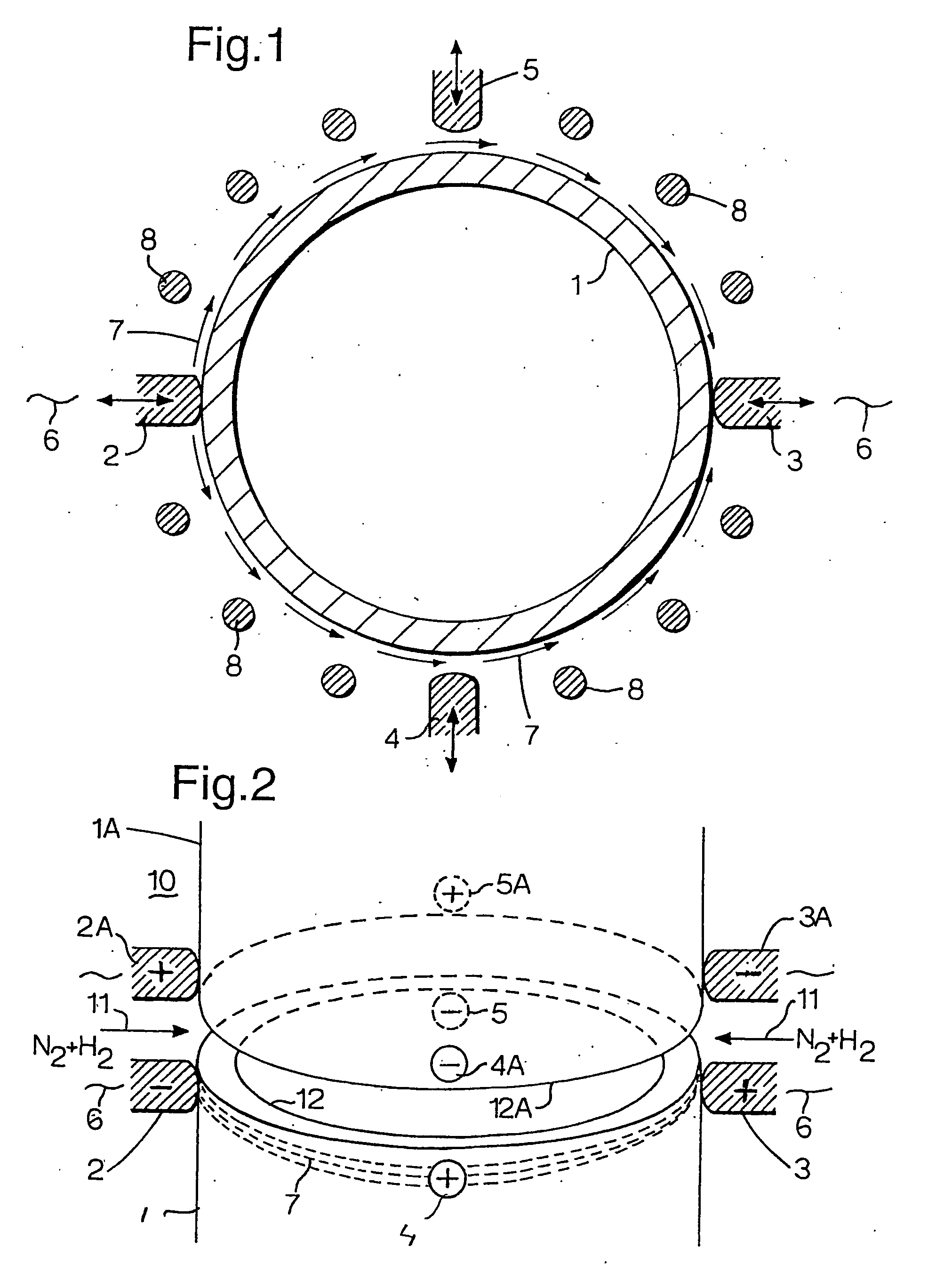
[0016]FIG. 1 depicts a cross-sectional view of a tubular end which is heated by two pairs of diametrically opposite electrodes;

[0017]FIG. 2 depicts a three-dimensional view of the tubular depicted in FIG. 1 before it is connected to another tubular by the forge welding method according to the invention;

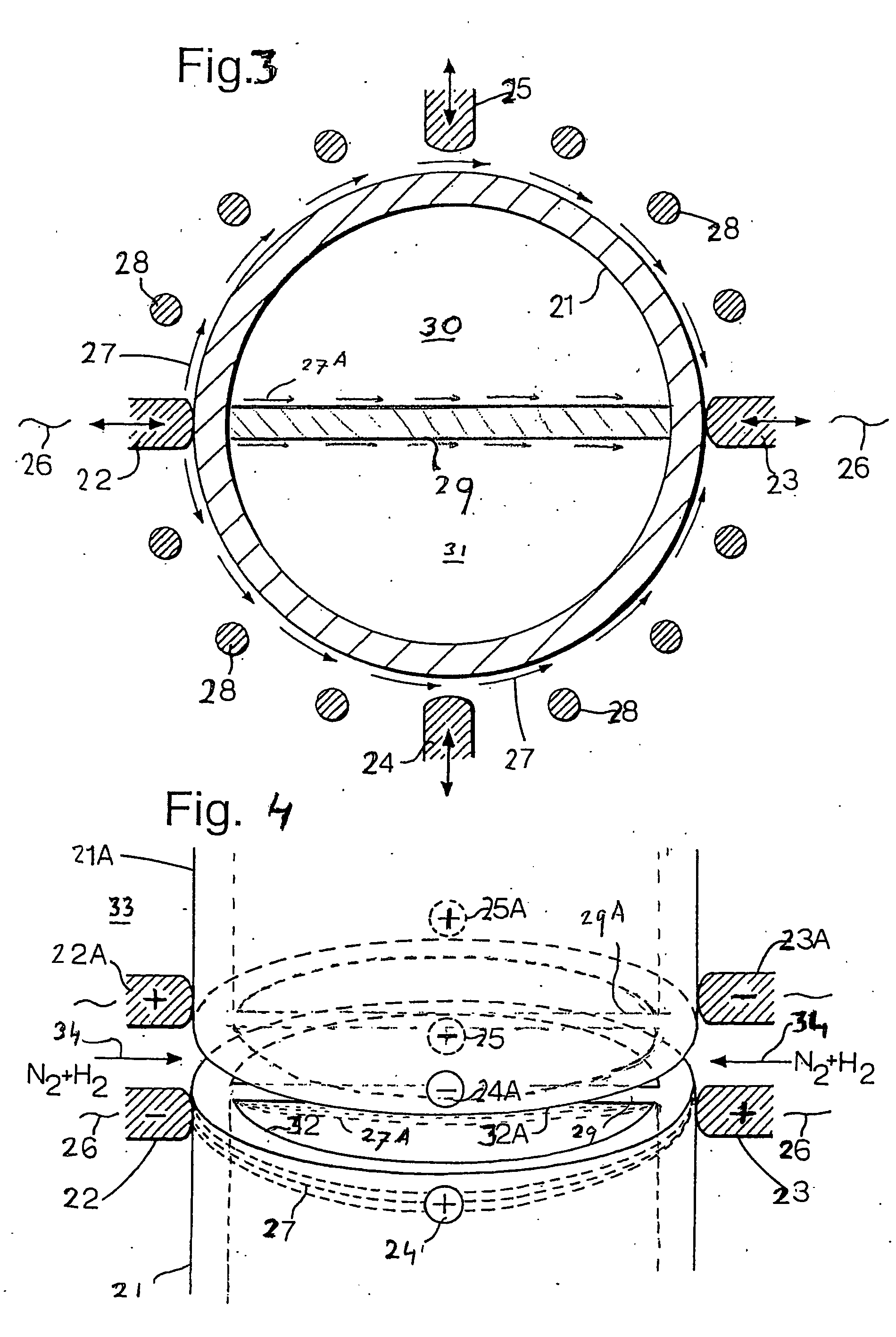
[0018]FIG. 3 depicts a cross-sectional view of a multibore tubular end which is heated by two pairs of diametrically opposite electrodes;

[0019]FIG. 4 depicts a three-dimensional view of the multibore tubular depicted in FIG. 3 before it is connected to another multibore tubular by the forge welding method according to the invention; and

[0020]FIGS. 5-10 depict various multibore conduit configurations of which the ends can be heated in a substantially uniform manner by using assemblies of three or more electrodes in accordance with the invention.

[0021] Re...


PUM

PropertyMeasurementUnit
Angleaaaaaaaaaa
Angleaaaaaaaaaa
Angleaaaaaaaaaa

Abstract

A method for interconnecting tubulars by forge welding involves arranging the tubular ends that are to be interconnected at a distance, up to a few millimeters from each other in a shield gas chamber, into which a reducing non-explosive flushing fluid mixture (e.g. N2+H2) is injected; heating each tubular end within the space by means of at least three electrodes that are pressed at circumferentially spaced intervals against the wall of each tubular, adjacent to the tubular end such that a high frequency electrical current is transmitted in a substantially circumferential direction through the tubular segments between the electrodes; and moving the thus uniformly heated tubular ends towards each other until a forge weld is formed between the heated tubular ends.

Description

BACKGROUND OF THE INVENTION [0001] The invention relates to a method and system for interconnecting tubulars by forge welding. It is known from U.S. Pat. No. 4,669,650 to forge weld tubular ends in a reducing environment, wherein a flushing gas, for example hydrogen having less than 100 ppm H2O and / or O2 is flushed around the heated tubular ends to inhibit corrosion and to reduce and flush off an oxidized skin. A disadvantage of using hydrogen as flushing gas is that it will react with oxygen in the atmosphere in an explosive fashion so that it cannot be used in hazardous areas such as on an offshore oil and / or gas production platform or on an oil and / or gas well drilling rig. This prior art reference mentions on page 2, lines 65-68 that instead of using a reducing gas an inert gas may be used as flushing gas and discloses that the tubular end may be heated by means of an induction coil or by means of an unspecified method of high frequency heating. [0002] International patent appli...

Claims


Application Information

Patent Timeline
IPC IPC(8): B23K11/02B23K20/02B23K20/14
CPCB23K11/02B23K13/046B23K20/14B23K20/028B23K20/023
Inventor ALFORD, ROBERT ANDREWCOLE, ANTHONY THOMASDIMITRIADIS, KLISTHENIS
Owner SHELL OIL CO
Why Eureka
Try Eureka