
Detachable on package voltage regulation module

a voltage regulation module and package technology, applied in the field of computer systems, can solve the problems of increasing power consumption, corresponding increase in power consumption, and general insufficient voltage conditioning provided by the power supply for powering critical components,

Inactive Publication Date: 2005-05-05
INTEL CORP
View PDF4 Cites 35 Cited by
  • Summary
  • Abstract
  • Description
  • Claims
  • Application Information

AI Technical Summary

Benefits of technology

The patent text describes a new way to cool computer components using a detachable voltage regulation module. This module is designed to improve power conditioning and prevent overheating of the motherboard. The invention solves the problem of traditional voltage regulation modules being mounted on the motherboard, which causes thermal stresses and connection failures due to the high power consumption of processor components. The new module is designed to be easily detached from the motherboard and connected to the processor using a separate connector, reducing the risk of failure. The invention also includes specific interconnect layouts and cooling mechanisms to improve the performance and reliability of the computer system.

Problems solved by technology

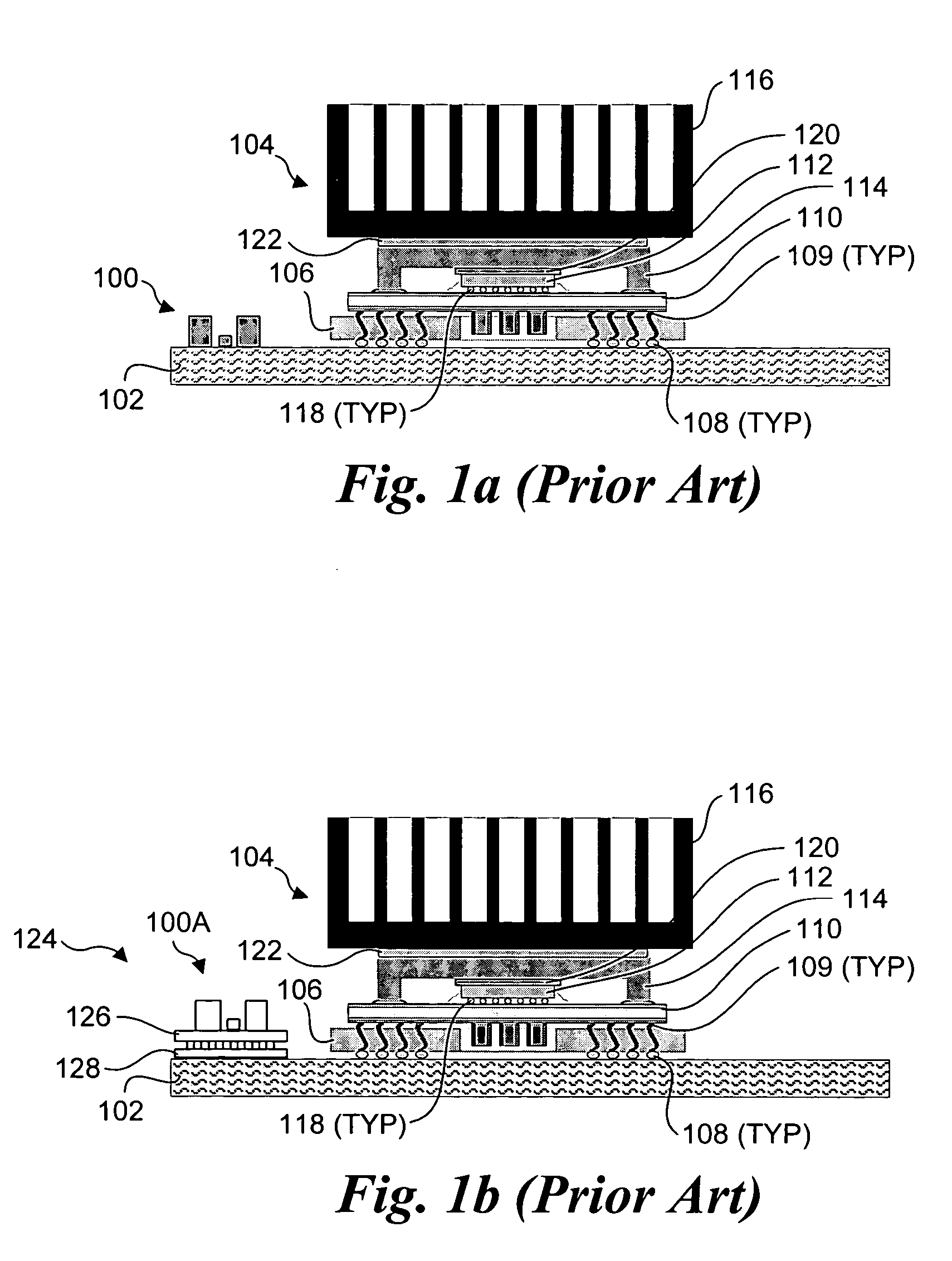
However, the voltage conditioning provided by the power supply is generally insufficient for powering critical components, such as the system processor(s).
With the ever-increasing processor speeds, a corresponding increase in power consumption has followed.
Since the supply voltage (e.g., 3.3 volts) to the processor must remain low, the heat generated via the power traces in the motherboard has increased in parallel with the increase in processor power consumption.
This leads to overheating of the motherboard power traces and thermal stresses on solder connections 108 and / or the socket connections.
Other drawbacks relate to mechanical considerations.
These resonances may, in turn, be coupled into the connection between the VRM and the motherboard, leading to connection failures.

Method used


Image

  • Detachable on package voltage regulation module
  • Detachable on package voltage regulation module
  • Detachable on package voltage regulation module

Examples


Embodiment Construction

[0017] Embodiments of a detachable on package voltage regulation module are described herein. In the following description, numerous specific details are set forth to provide a thorough understanding of embodiments of the invention. One skilled in the relevant art will recognize, however, that the invention can be practiced without one or more of the specific details, or with other methods, components, materials, etc. In other instances, well-known structures, materials, or operations are not shown or described in detail to avoid obscuring aspects of the invention.

[0018] Reference throughout this specification to “one embodiment” or “an embodiment” means that a particular feature, structure, or characteristic described in connection with the embodiment is included in at least one embodiment of the present invention. Thus, the appearances of the phrases “in one embodiment” or “in an embodiment” in various places throughout this specification are not necessarily all referring to the ...


PUM


Abstract

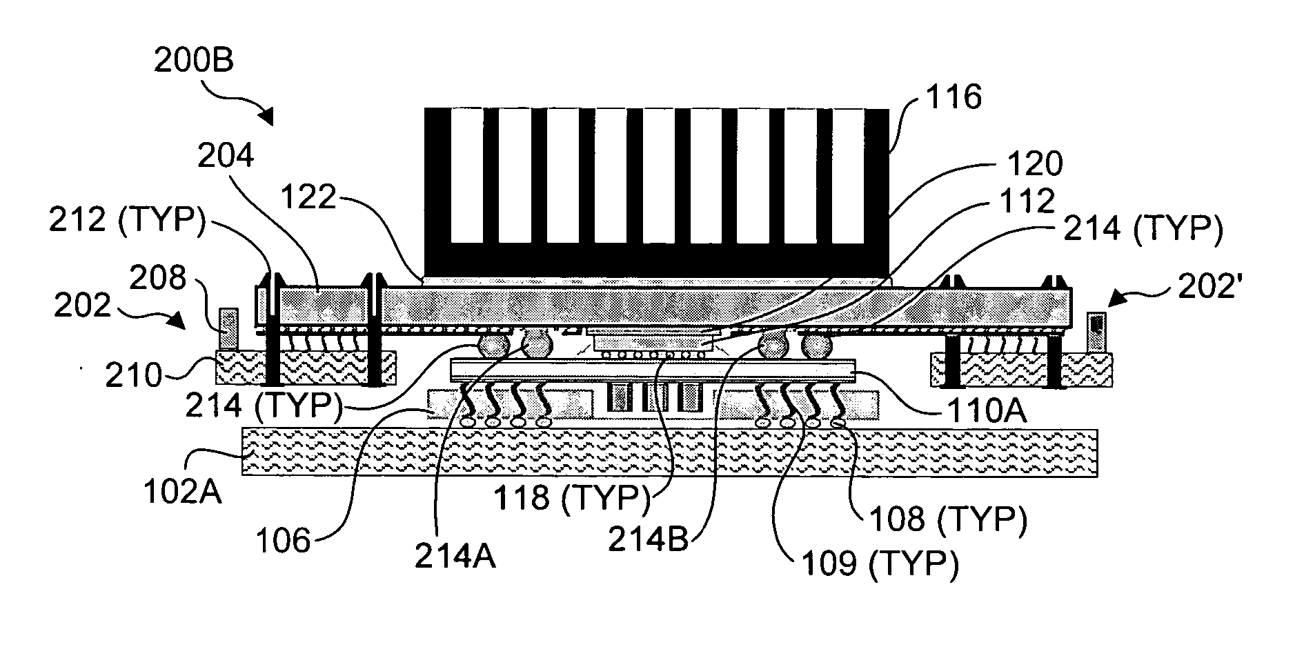
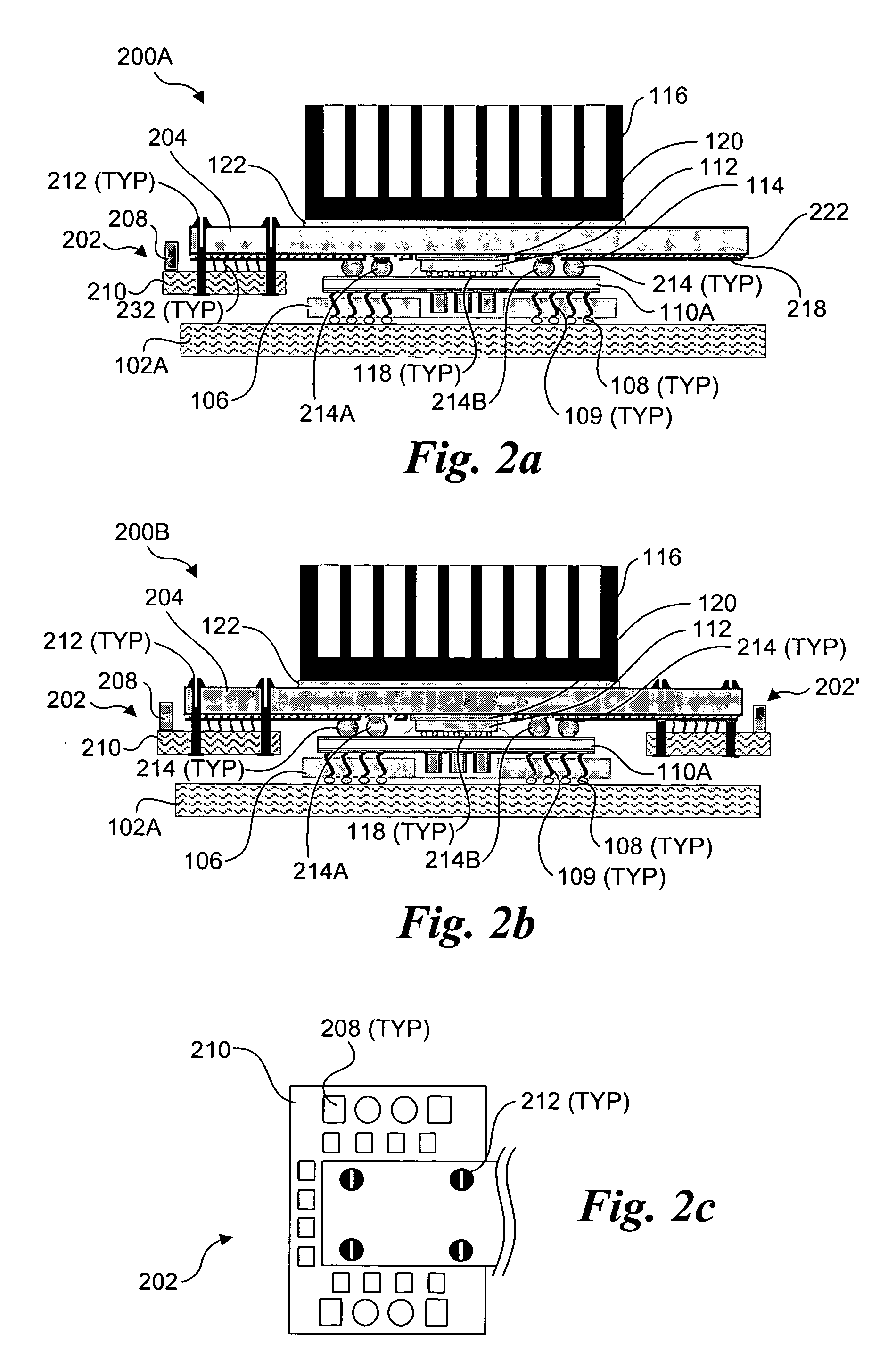
An integrated circuit (IC) package that includes an on-package voltage regulation module (VRM). An IC die is flip-bounded to a substrate having a plurality of connections to couple to a socket or to be mounted directly to a circuit board. An integrated heat spreader (IHS) is thermally coupled to the IC die and coupled (both electrically and mechanically) to the substrate. A VRM is coupled to the IHS. The IHS, which serves as an interconnect member, includes interconnect provisions for electrically coupling the VRM to the substrate. In one embodiment, the body of the IHS serves as a ground plane, while a separate interconnect layer includes electrical traces for routing electrical signals between the VRM and substrate. The VRM may comprise a detachable package that is coupled to the IHS via one of several means including fasteners, edge connectors and a parallel coupler.

Description

FIELD OF THE INVENTION [0001] The field of invention relates generally to computer systems and, more specifically but not exclusively relates to packaging schemes for voltage regulation modules. BACKGROUND INFORMATION [0002] An important aspect of any computer system is power provisioning. Generally, regulated power must be supplied to various system components, such as peripheral devices, circuit boards, and integrated circuits. Under a typical configuration, a power supply is used to convert alternating current (AC) input to various direct current (DC) voltage outputs that are supplied to the computer system. The power supply provides a certain level of power conditioning that is suitable for many of the system components. However, the voltage conditioning provided by the power supply is generally insufficient for powering critical components, such as the system processor(s). [0003] In order to provide enhanced power conditioning, many systems employ a specially-configured voltage...

Claims


Application Information

Patent Timeline
Patent Type & Authority Applications(United States)
IPC IPC(8): G06F1/26H01L23/12H01L23/36H01L23/367H05K1/02H05K1/18
CPCH01L23/36H05K1/0262H05K2201/10325H05K2201/1053H05K2201/10689H01L2224/16225H01L2224/32225H01L2924/16152H01L2224/73253H01L2224/73204H01L2924/00H01L25/04
Inventor MILLIK, DEBENDRAPATEL, PRIYAVADAN R.
Owner INTEL CORP
Learn More