Light source assembly for vehicle external lighting

a technology for external lighting and light source parts, which is applied in the direction of landing aids, lighting and heating apparatus, and light support devices, etc., can solve the problems of frequent maintenance, limited and limited service life of incandescent lamps in vehicle exterior lighting applications

Inactive Publication Date: 2005-05-05
L 3 COMM CORP
View PDF16 Cites 64 Cited by
  • Summary
  • Abstract
  • Description
  • Claims
  • Application Information

AI Technical Summary

Benefits of technology

[0012] It is therefore an object of the present invention to provide a navigation light for

Problems solved by technology

The lifetime of incandescent lamps, especially in military aircraft exterior lighting applications, is limited, and replacement of incandescent lamps in the exterior lighting fixtures of vehicles, in particular aircraft, is a frequent maintenance task.
However, LEDs are not perfect converters of electrical energy into light energy, and some energy always will be lost as waste heat.
This creates a problem for possible use of LEDs in aircraft navigation lighting, because the heat created increases the temperature of the LEDs, and, for a given drive voltage, the hotter an LED gets, the less light that LED emits.
The problem is even greater in the area of navigation light aviation applications, because to achieve luminous intensity levels conforming to FAA/ICAO regulations a number of high intensity LED diodes (individual light emitters) must be integrated and co-packaged.
However, the added LEDs ge

Method used


Image

  • Light source assembly for vehicle external lighting
  • Light source assembly for vehicle external lighting
  • Light source assembly for vehicle external lighting

Examples


Embodiment Construction

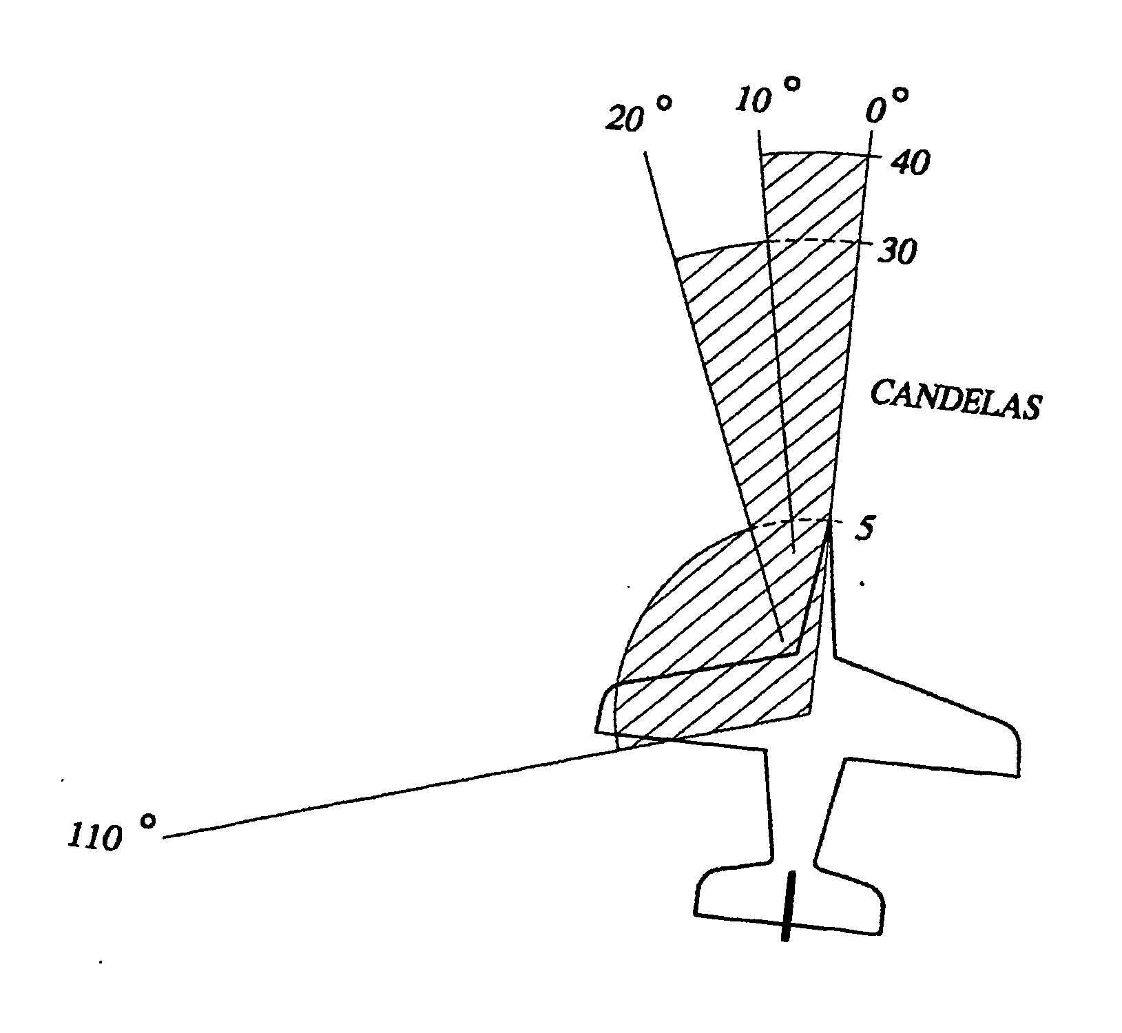
[0041] Referring to FIG. 1, all aircraft flying in civilian airspace are required to be equipped with visible navigational lights to allow them to see each other at night or in conditions of bad visibility. The FAA has defined the parameters for acceptable navigational light intensity based on the angle of viewing thereof. A navigational light on top of an aircraft must project at least 40 candelas luminous intensity directly ahead, i.e. zero degrees, and in a 10-degree angular spread to the side of the plane. Between 10 and 20 degrees off the nose of the plane, 30 candelas luminous intensity are required. Between 20 and 110 degrees, an illumination of only 5 candelas is required.

[0042] Military aircraft are also required to have such visible navigation lighting systems for operation in civilian areas in a non-covert, visible mode. Accordingly, even military aircraft are equipped with a number of navigational lights, which have traditionally been a plurality of incandescent bulbs. ...


PUM


Abstract

An aircraft light assembly comprises a light apparatus configured to be supported in a space on the body of an aircraft. The apparatus has one or more light emitting diodes (13) generating visible light and an outer structure overlying the LEDs. The outer structure includes a light transmission portion through which visible light from the LEDs can pass, and a metallic portion with an outer surface exposed to the external airflow. A heat-transmitting connection thermally links the LEDs to the metallic portion so that heat from the LEDs flows to the outer surface and is dissipated to the external airflow. The light assembly is configured to be secured in a conventional socket for an incandescent navigation light bulb and to receive the electrical current supplied thereto by the aircraft electrical system. Civilian applications of the unit have only visible LEDs. When the unit is for a military aircraft, it has electric circuitry connected with a visible light source and an IR light source, and the electric circuitry is configured to process the input current from the socket and based thereon operate in either a visible mode or covert IR mode. Where the current is in one electrical state, such as for example a certain voltage, the electric circuit sends power only to the visible light source. When the current is in a different electrical state, e.g., a different voltage level, the circuitry sends power only to the IR source, and no visible light is emitted. Different input current voltages or characteristics are also used to cause the IR emitter to flash in various patterns that can be programmed into the unit. All control may be accomplished over a single pair of wires, as in existing systems that do not have IR mode capability. To upgrade existing aircraft, light source units a shaped to fit in the apertures for existing lenses over incandescent navigational fixtures.

Description

RELATED APPLICATIONS [0001] This application is a continuation-in-part of U.S. patent application Ser. No. 09 / 665,600 entitled DUAL MODE LIGHT SOURCE FOR AIRCRAFT EXTERNAL LIGHTING filed on Sep. 19, 2000 by inventors John J. Martin and Cary H. Leach, which is still pending and herein incorporated by reference. [0002] This application also asserts priority of U.S. provisional patent application Ser. No. 60 / 356,854 filed Feb. 13, 2002.FIELD OF THE INVENTION [0003] This invention relates to navigation light sources provided for aircraft that are used to render the aircraft visible, and more particularly to navigation lights for civilian or military aircraft that use light emitting diodes (LEDs) to generate visible light. The invention also relates to apparatus and methods of upgrading the navigation lights of existing aircraft. BACKGROUND OF THE INVENTION [0004] The aviation authorities of many countries require that commercial aircraft, and also military aircraft, when in civilian air...

Claims


Application Information

Patent Timeline
IPC IPC(8): B64D47/06
CPCB64C2027/8236B64D2203/00B64D47/06F21W2107/30H05B45/10H05B45/3577H05B45/3725
Inventor MARTIN, JOHN J.
Owner L 3 COMM CORP
Why Eureka
Try Eureka