Storage device based on phase-change modulated luminescence

a technology of phase-change modulation and storage device, which is applied in the direction of optical recording/reproducing/erasing methods, mechanical recording, instruments, etc., can solve the problems of affecting the luminescent properties of the luminescent layer, requiring processing temperatures and conditions harmful to the phase-change layer, and requiring aluminescent layers

Inactive Publication Date: 2005-05-05
HEWLETT PACKARD DEV CO LP
View PDF4 Cites 11 Cited by
  • Summary
  • Abstract
  • Description
  • Claims
  • Application Information

AI Technical Summary

Problems solved by technology

The problem with this light monitoring approach is that the luminescent layer must be manufactured on top of the phase-change layer, where “on top” refers to placing a layer further away from the base layer, or outward from the base layer of the medium.
Placing a luminescent layer on top of the phase-change layer can require processing temperatures and conditions harmful to the phase-change layer.
High temperatures and / or bombardment by high energy electrons can adversely affect the luminescent properties of the luminescent layer.
Another potential disadvantage of this scheme is that the photodetector is below the phase-change layer, which can make manufacturing more difficult.
Other problems may arise if too much light is absorbed or reflected in unwritten portions of the phase-change layer below a written bit intended to be transmissive, or if too much light internally reflects at the bottom surface of the phase-change layer.
Also, in certain designs, significant light may be lost through the top surface of the luminescent layer rather than reflected down toward the phase-change layer where it can add to the signal.

Method used


Image

  • Storage device based on phase-change modulated luminescence
  • Storage device based on phase-change modulated luminescence
  • Storage device based on phase-change modulated luminescence

Examples


Embodiment Construction

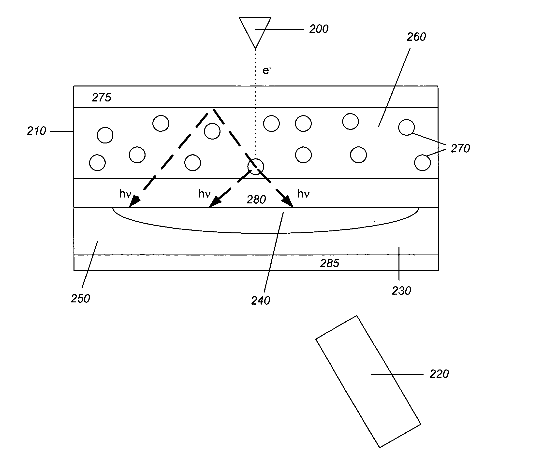
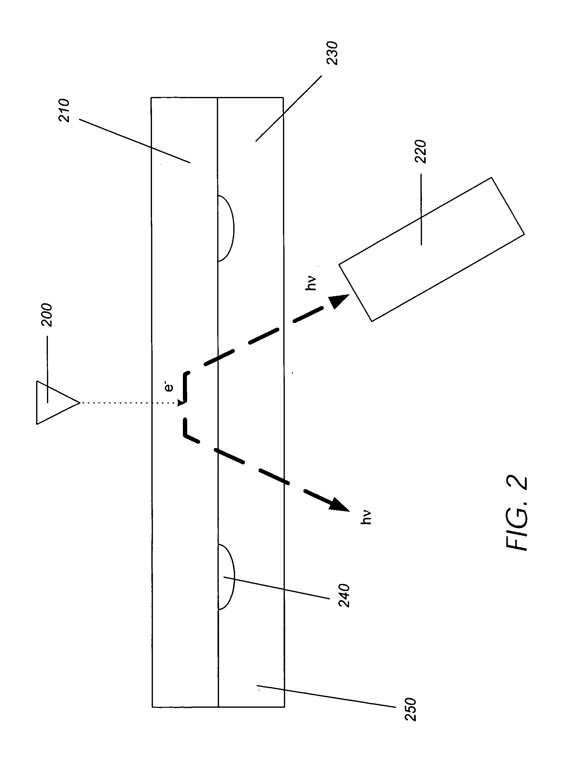
[0032]FIG. 2 shows a cross-sectional view of an ultra-high-density data storage device. The device includes a beam source 200, which may be a device capable of emitting a light beam or an electron beam, e−, of either a high or low power density. FIG. 2 illustrates an electron beam, e−, being transmitted by the beam source 200. As used herein, the term “beam source” may apply to a device capable of emitting an optical beam, such as a light beam, or an electron beam, and embodiments described and drawings included are not intended to be limiting as to the type of beam that may be emitted from the beam source unless otherwise indicated. The electron beam, e−, illustrated in FIG. 2 can be focused to a sub-micron-scaled spot size.

[0033] As understood in the art, beam sources 200 are capable of emitting an electron beam focusable to a nanometer-scaled spot size. The beam source 200 may be a field emitter, Schottky emitter, or another such device capable of emitting energy in the form of ...


PUM

PropertyMeasurementUnit
luminescentaaaaaaaaaa
phaseaaaaaaaaaa
phase-aaaaaaaaaa

Abstract

A media storage device is provided. The device comprises different configurations of a luminescent layer comprising a luminescent material capable of emitting light while being bombarded by a beam from a beam transmitter, a detector for detecting the light emitted from the luminescent layer, and a phase-change layer located proximate the luminescent layer. The phase-change layer is able to transform from a first phase to a second phase. Light emitted from the luminescent layer and received by the detector materially differs when the phase-change layer transforms from the first phase to the second phase.

Description

BACKGROUND OF THE INVENTION [0001] 1. Field of the Invention [0002] The present invention relates generally to the field of thermal writing of high density data media, and more particularly to the specific composition and methods of forming high density data recording products. [0003] 2. Description of the Related Art [0004] Phase-change media are a widely available means for providing high density data storage, and such media may include CD-RW, DVD-RAM, and DVD-RW formats, among others. In this type of media, data is stored at a particular location, typically micron sized, and storage and erasure occurs based on the microstructure of the target region. FIG. 1 illustrates an ultra-high-density data storage device disclosed in U.S. Pat. No. 5,557,596 to Gibson et al. (the '596 patent). The ultra-high-density data storage device includes a set of field emitters 100, a data storage layer 110 that is located below the field emitters 100, a micromover 120 that holds the data storage laye...

Claims


Application Information

Patent Timeline
Patent Type & Authority Applications(United States)
IPC IPC(8): G11B7/00G11B7/0045G11B7/005G11B7/257G11B7/258G11B9/00G11B9/10G11B11/08
CPCB82Y10/00G11B2007/25716G11B7/2578G11B7/258G11B9/10G11B9/14G11B9/1463G11B11/08G11B2005/0021G11B2007/25706G11B2007/25708G11B2007/2571G11B2007/25713G11B2007/25715G11B7/00454
Inventor GIBSON, GARY
Owner HEWLETT PACKARD DEV CO LP
Why Eureka
Try Eureka