Method for controlling a multi-pulse record waveform at high velocity in a phase change optical medium

Inactive Publication Date: 2005-05-05
RICOH KK
View PDF14 Cites 0 Cited by
  • Summary
  • Abstract
  • Description
  • Claims
  • Application Information

AI Technical Summary

Benefits of technology

[0017] In the optical recording method and apparatus of the present invention, the driving power is applied to the light source to control emission of a light beam to the recording layer of the optical storage medium, the driving power including a sequence of mark and space portions, each mark potion having a pulse width that corresponds to a multiple of the period T of the write clock. The waveform of each mark portion of the driving power includes the front-end portion, the multi-pulse portion and the tail-end portion, the front-end portion having the first pulse width t1 with the write level Pw and starting from the erase level Pe, the multi-pulse portion including the write pulses each having the second pulse width t2 with the write level Pw and the third pulse width t3 with the base level Pb, the multi-pulse portion having the duty ratio z=t2/(t2+t3), and the tail-end portion having the fourth pulse width t4 with the

Problems solved by technology

The recording speeds of the media in this range require a relatively long time to record information onto the med

Method used


Image

  • Method for controlling a multi-pulse record waveform at high velocity in a phase change optical medium
  • Method for controlling a multi-pulse record waveform at high velocity in a phase change optical medium
  • Method for controlling a multi-pulse record waveform at high velocity in a phase change optical medium

Examples


Example

[0024] A description will now be provided of preferred embodiments of the present invention with reference to the accompanying drawings.

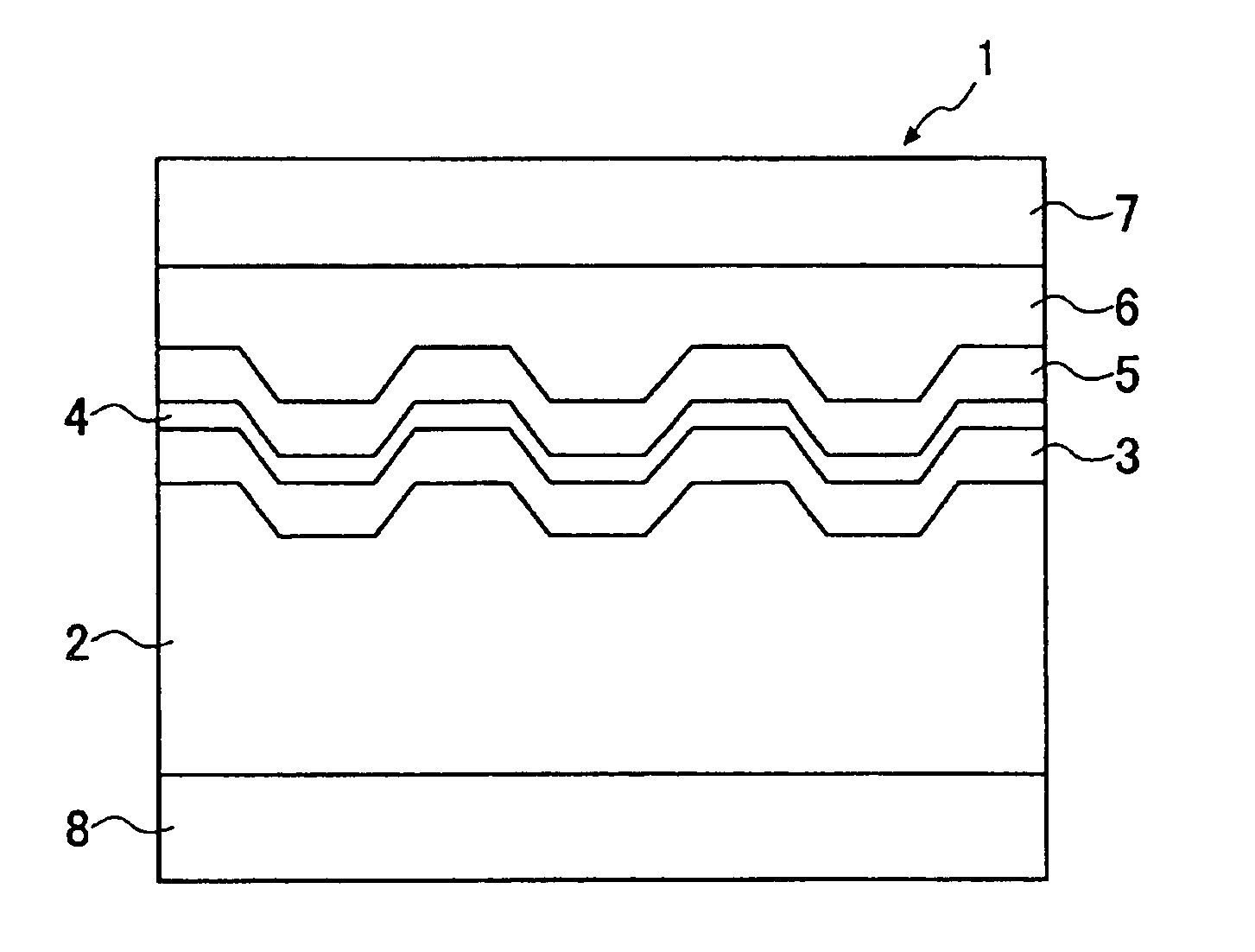
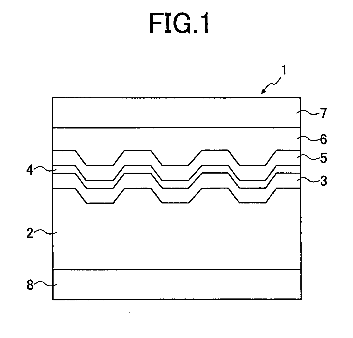
[0025]FIG. 1 is a cross-sectional diagram of one preferred embodiment of the optical storage medium of the invention.

[0026] The optical storage medium of the present embodiment is a rewritable phase-change medium (CD-RW) in which a recording layer of a phase-change material is formed on a substrate. As shown in FIG. 1, in the storage medium 1 of this embodiment, a substrate 2, a lower protective layer 3, a recording layer 4, an upper protective layer 5, and a reflection / heat-radiation layer 6 are provided. The lower protective layer 3, the recording layer 4, the upper protective layer 5 and the reflection / heat-radiation layer 6 are deposited, in this order, on the front surface of the substrate 2. Further, an over-coat layer 7 may be provided on the reflection / heat-radiation layer 6, and a hard-coat layer 8 may be provided on the back surface of t...


PUM


Abstract

In an optical recording method and apparatus of the present invention, a driving power is applied to a light source to control emission of a light beam to a recording layer of an optical storage medium, the driving power including a sequence of mark and space portions, each mark portion having a pulse width that corresponds to a multiple of a period T of a write clock. A multi-pulse waveform of each mark portion of the driving power includes a front-end portion, a multi-pulse portion and a tail-end portion, the front-end portion having a first pulse width t1 with a high-power write level Pw and starting from a middle-power erase level Pe, the multi-pulse portion including write pulses each having a second pulse width t2 with the write level Pw and a third pulse width t3 with a low-power base level Pb, the multi-pulse portion having a duty ratio z=t2/(t2+t3), and the tail-end portion having a fourth pulse width t4 with the base level Pb and ending at the erase level Pe. The waveform is controlled, when a linear velocity of rotation of the medium is set in a range from 5 m/s to 28 m/s, such that the first pulse width t1 ranges 0.1T to 1T and the fourth pulse width t4 ranges 0.2T to 1.3T.

Description

BACKGROUND OF THE INVENTION [0001] 1. Field of the Invention [0002] The present invention relates to an optical recording method and apparatus that records information onto an optical storage modium at a high speed by emitting a light beam to a recording layer of the storage medium. Further, the present invention relates to an optical storage medium that stores information recorded by using the optical recording method and apparatus. [0003] 2. Description of the Related Art [0004] Recently, optical storage media, including CD-R (compact disk recordable), CD-RW (compact disk rewritable) and so on, become widespread. Bach storage medium is provided for recording information thereon by focusing a light beam onto a recording layer of the medium and changing the phase of the recording layer material. [0005] As disclosed in Japanese Laid-Open Patent Application No.63-29336, an optical recording method that records information onto a recording layer of an optical recording medium by emitti...

Claims


Application Information

Patent Timeline
IPC IPC(8): G11B7/0045G11B7/0055G11B7/125
CPCG11B7/0045G11B7/126G11B7/0062
Inventor NAKAMURA, YUKI
Owner RICOH KK
Why Eureka
Try Eureka