
Laser and detector device

Inactive Publication Date: 2005-05-05
CUFER ASSET LTD LLC
View PDF14 Cites 18 Cited by
  • Summary
  • Abstract
  • Description
  • Claims
  • Application Information

AI Technical Summary

Benefits of technology

[0024] We have devised a way to integrate a detector function with a device so as to not require a separate laser and detector arrangement, can be used. Our approach is usable with existing semiconductor lasers (including those purchased from third parties), it does not degrade the output of the laser, nor does it affect the mode of the output beam.
[0025] In overview, we integrate a power monitoring structure with a laser structure on the non-emission side of the laser. This monitoring structure enables monitoring of the laser over time in order to provide feedback regarding laser operation to, for example, maintain constant power output and / or accurately detect when an individual laser output has reduced to a point that compensation is required, that the laser has failed or degraded to the point of being effectively “dead” with respect to the application it is being used for.
[0026] Performing the sampling via a structure located on the non-emission side of the laser provides advantages, for example, one or more of the following: it is easily usable with both lasers of the top emitting (away from the laser substrate) and bottom emitting (toward the laser substrate) type, there is little to no feedback from outside the laser itself, the structure does not interfere with the laser output, the basic structural design for the laser can stay essentially, if not actually, the same, it allows for close integration / hybridization of the lasers with chips containing other electronic integrated circuits, and is compatible with very dense integration of the laser devices.

Problems solved by technology

For instance, some of these advantages are mutually contradictory, in that they cannot be simultaneously present in a single embodiment.

Method used


Image

  • Laser and detector device
  • Laser and detector device
  • Laser and detector device

Examples


Embodiment Construction

[0038] Laser structures are very sensitive to their design and fabrication, and the laser designs presently in use have been optimized over many years to get adequate functionality. Thus, people seeking to use those lasers are reluctant to deviate from or alter those designs for fear of creating devices that do not work properly. Moreover, we have realized that such devices can be used without employing a structure that can interfere with the laser's output.

[0039] For ease of explanation herein, the side of the laser having the mirror with the lower reflectivity, which corresponds to the mirror through which the laser is intended to emit during operation is referred to as the “active” side. The side opposite the emission (i.e. active) side of the laser is referred to herein as the “passive side” of the laser and the mirror on that side is referred to as the passive side mirror.

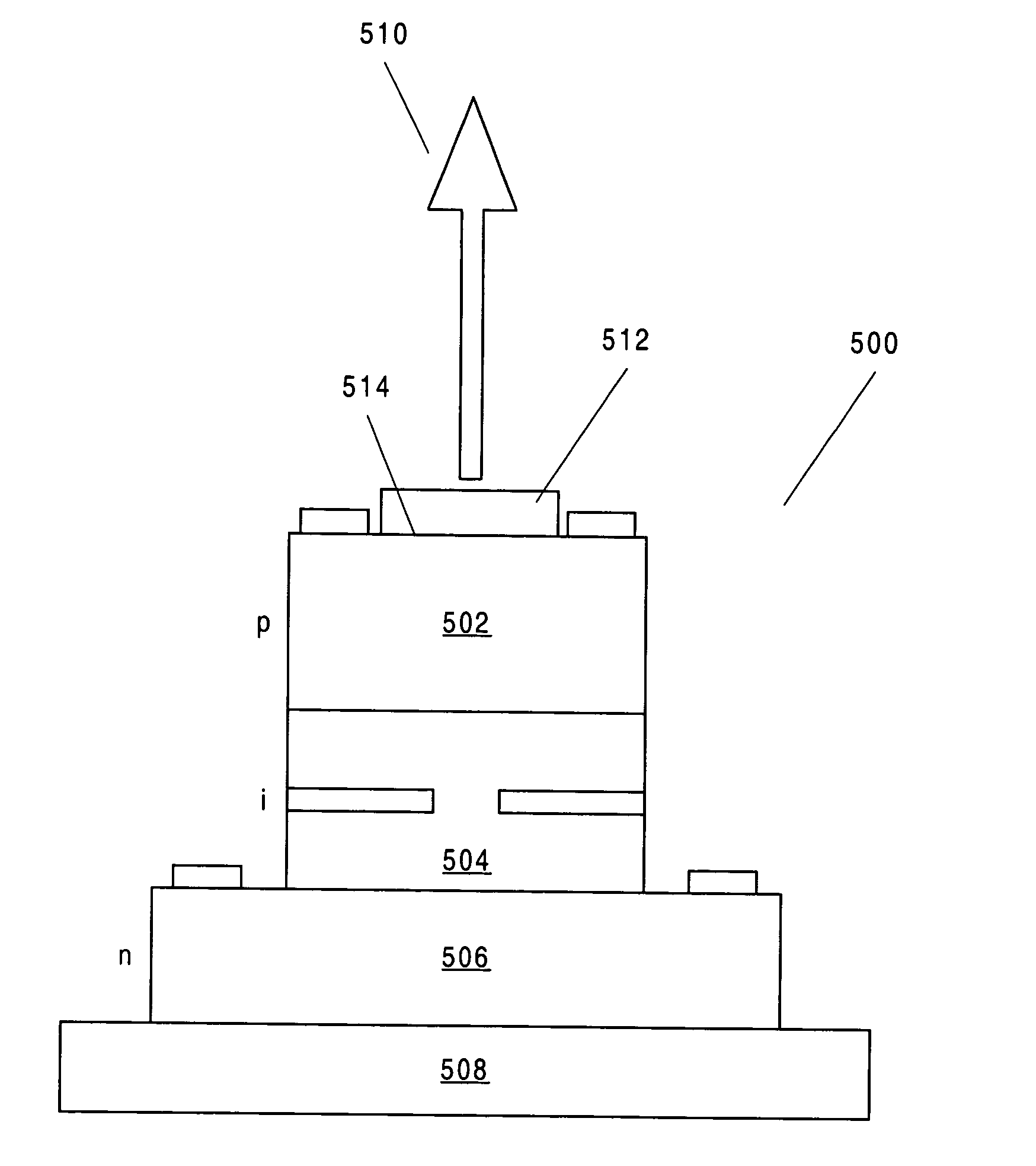
[0040]FIG. 9 is a simple representation of a conventional bottom emitting VCSEL 900 comprising a pair of ...


PUM


Abstract

A detector is disposed on the passive side of a laser to detect photon leakage through the passive side mirror and measure as current created in the detector via a Schottkey contact.

Description

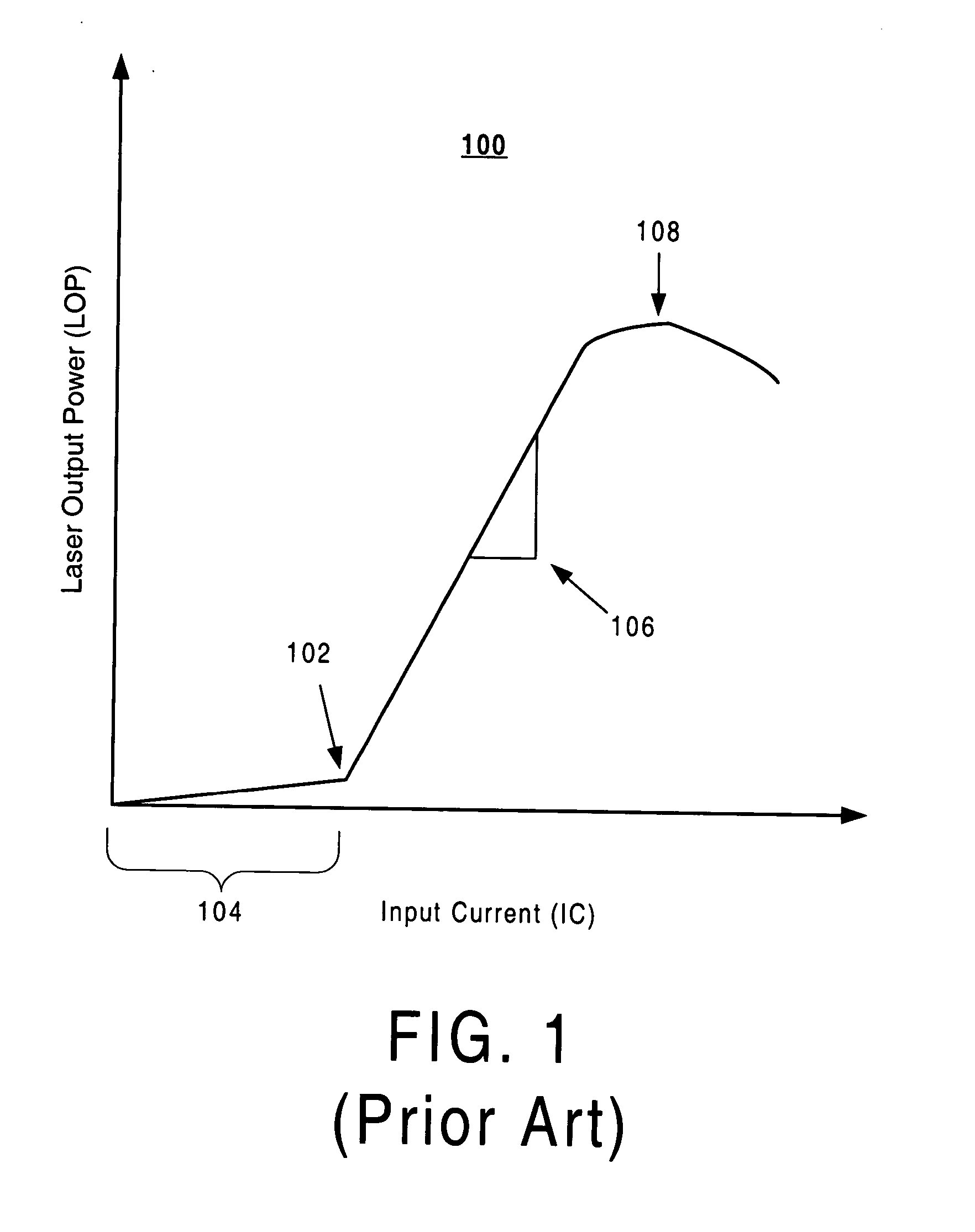
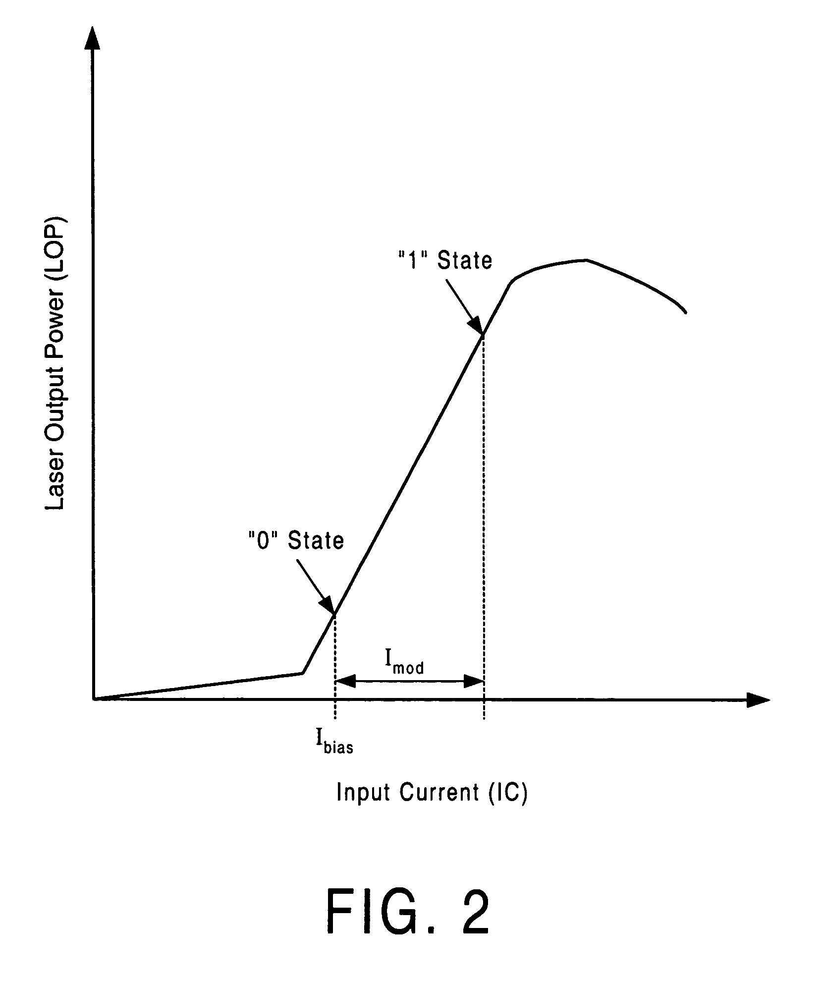
FIELD OF THE INVENTION [0001] This invention relates to optical devices and, more particularly to lasers and photodetectors. BACKGROUND OF THE INVENTION [0002] Typical lasers are comprised of two mirrors and an active region cavity. In Vertical Cavity Surface Emitting Lasers (VCSELS), there are two mirrors, a bottom mirror (which is larger / more reflective) and a top mirror, through which the light is output. In addition there is an active region, in between the two, where the light is generated. The mirrors are typically “doped”, which means that impurities are inserted into the material to make them electrically conductive. The active region is typically “intrinsic”, meaning that it is not doped with the impurities to get significant conductivity. [0003] Electrically pumped lasers take electrical input current and convert it to light power output. How much light a laser emits as a function of how much current is input depends upon several parameters. First is the details of the las...

Claims


Application Information

Patent Timeline
IPC IPC(8): G02BH01S5/00H01S5/026H01S5/183
CPCH01S5/0207H01S5/0224H01S5/02272H01S5/18308H01S5/0264H01S5/0425H01S5/18305H01S5/02276H01S5/0208H01S5/18386H01S5/04257H01S5/0234H01S5/02345H01S5/0237H01S5/183
Inventor TREZZA, JOHNDIAGNE, MOHAMED
Owner CUFER ASSET LTD LLC
Learn More