Method and apparatus for direct RF to digital converter

Inactive Publication Date: 2010-12-02
PANASONIC CORP
View PDF10 Cites 0 Cited by
  • Summary
  • Abstract
  • Description
  • Claims
  • Application Information

AI Technical Summary

Benefits of technology

[0010]In one embodiment, the decomposing circuit includes a single-to-differential circuit for decomposing the incoming high frequency signal into a first and a second signal having opposite polarities. Each of the first and the second incoming signals is then processed through a multistage cascading logic circuit which reduces the frequency of the respective signals to provide a plurality of low-frequency digita

Problems solved by technology

A conventional down-converting process requires multiple processing elements which can consume an ever increasing portion of the circuit's footprint and can be otherwise inefficient.
The frequency information is used by phase detector 110 to iteratively determine the phase of signal S. A drawback of the circuit of F

Method used


Image

  • Method and apparatus for direct  RF to digital converter
  • Method and apparatus for direct  RF to digital converter
  • Method and apparatus for direct  RF to digital converter

Examples


Embodiment Construction

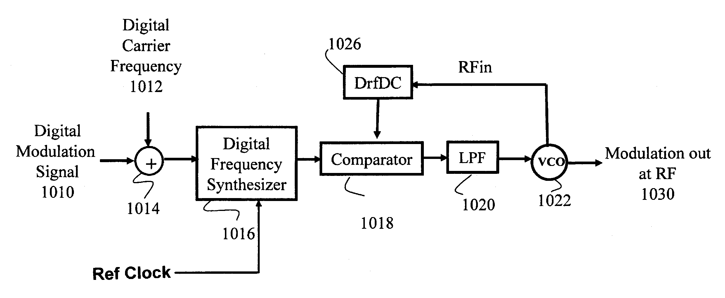
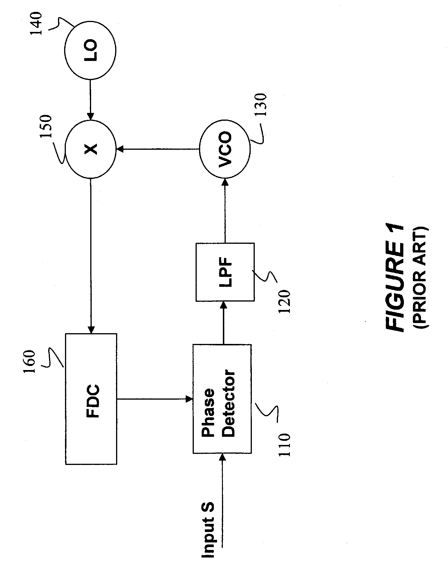
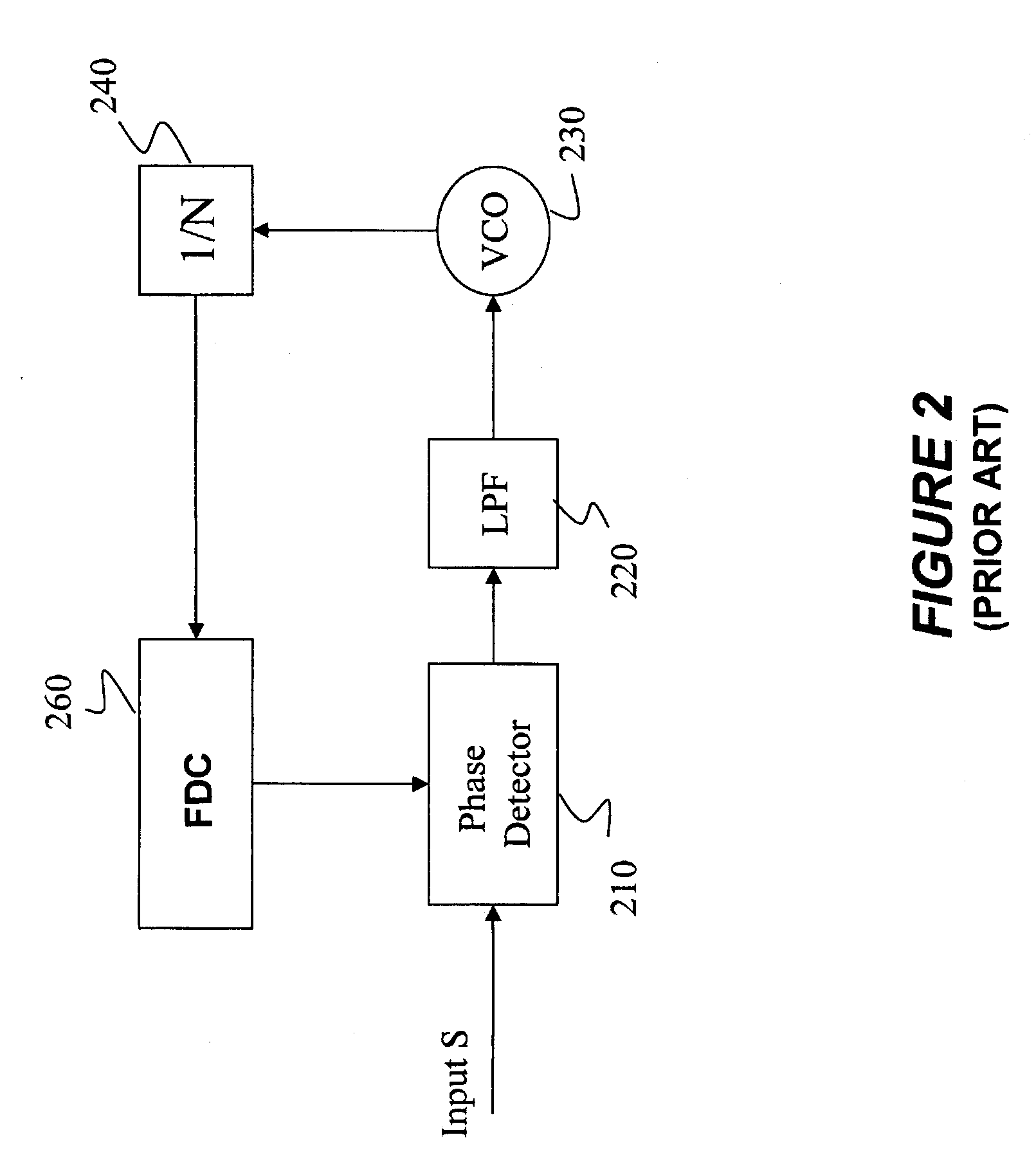
[0035]The present invention provides a direct RF-to-digital converter (“DrfDC”) which enables directly decomposing a high frequency signal into a plurality of digital data streams for signal processing. The present invention does not require a local oscillator, a mixer or an offset PLL which have been used in conventional systems to obtain the same results. The front-end of the disclosed DrfDC decomposes the high frequency RF signal into several low frequency signals without loss of any information. The low frequency signals are processed by the back-end of the DrfDC and are converted into digital data streams. These digital data streams are then combined into one signal to represent the frequency of the input RF signal.

[0036]The digital data streams (even when combined into one signal) retain all of the level change information carried by the high frequency signal. The present invention operates with no information loss. Whereas the conventional system only captures the rising edge...


PUM


Abstract

The invention relates to a method and apparatus for decomposing a high frequency incoming signal into several low frequency signals without the loss of any information. The low frequency signals can define a plurality of digital data streams. The decomposing steps are implemented without processing the signal through a mixer or a local oscillator and without degrading the SNR. In a preferred embodiment, a decomposing circuit includes a single-to-differential converter for decomposing the incoming high frequency signal into a first and a second signal having opposite polarity. Each of the first and the second incoming signals is then processed through multistage cascading logic units which reduce the frequency of the respective signals to provide a plurality of low-frequency data streams. The resulting slow-speed data streams are combined to form a low-speed data stream containing all the information provided by the original high-frequency signal.

Description

BACKGROUND[0001]1. Field of the Invention[0002]The present invention provides an efficient mean for directly measuring frequency of an RF signal using low speed digital circuits and without the need to down-convert the (radio frequency) RF signal. More specifically, the present invention relates to a method and apparatus for decomposing an RF signal into a plurality of low frequency data streams without the use of extraneous circuit components such as local oscillators, mixers or offset phase-locked loops.[0003]2. Description of Related Art[0004]All RF communication systems require converting an incoming RF signal into a digital representation of the signal for further processing. The signal processor must also detect the frequency and the phase of the incoming signal and produce another signal that has a fixed relationship to the phase and frequency of the incoming signal. In conventional signal processing, a mixer and an offset phase-locked loop (“PLL”) are frequently used to down...

Claims


Application Information

Patent Timeline
IPC IPC(8): H04B1/38H04L27/00H04L27/06
CPCG01R23/02H03D3/001H04L27/0002
Inventor LIANG, PAUL CHENG-POTAKINAMI, KOJI
Owner PANASONIC CORP
Why Eureka
Try Eureka