
Method and detecting carrier shift amount in digital transmission signal, method of correcting carrier shift amount, and receiver employing these methods

a digital transmission signal and amount detection technology, applied in the field of improving the immunity of digital transmitters in transmission, can solve the problems of failure to align carriers, frequency can be normally corrected, and the control method cannot normally correct for a frequency shift. achieve the effect of improving transmission immunity

Inactive Publication Date: 2005-05-05
KOKUSA ELECTRIC CO LTD
View PDF10 Cites 10 Cited by
  • Summary
  • Abstract
  • Description
  • Claims
  • Application Information

AI Technical Summary

Benefits of technology

[0008] It is an object of the present invention to eliminate the foregoing disadvantages and to enable a received signal to be corrected for a frequency shift even when the frequency shift extends across ±2 carriers or more.
[0013] According to the present invention, a received signal can be normally corrected for a frequency shift suffered on a transmission path or the like, even if the frequency shift extends over ±2 carriers, thus improving immunity in the transmission.

Problems solved by technology

However, the foregoing control method for correcting a signal for a frequency shift implies the following problems.
The foregoing control method cannot normally correct for a frequency shift unless the amount of frequency shift is within certain limits.
Therefore, the control method has a problem in that it fails to align the carrier to a correct position if a frequency shift extends across two or more carriers though it successfully aligns the carrier to the correct position if a frequency shift extends over one carrier or less.
As described above, a problem experienced by the prior art control method described above is that the frequency can be normally corrected for a shift if the shift extends over ±1 carrier or less, whereas the frequency cannot be normally corrected for a shift if the shift extends over ±2 carriers or more.

Method used


Image

  • Method and detecting carrier shift amount in digital transmission signal, method of correcting carrier shift amount, and receiver employing these methods
  • Method and detecting carrier shift amount in digital transmission signal, method of correcting carrier shift amount, and receiver employing these methods
  • Method and detecting carrier shift amount in digital transmission signal, method of correcting carrier shift amount, and receiver employing these methods

Examples


Embodiment Construction

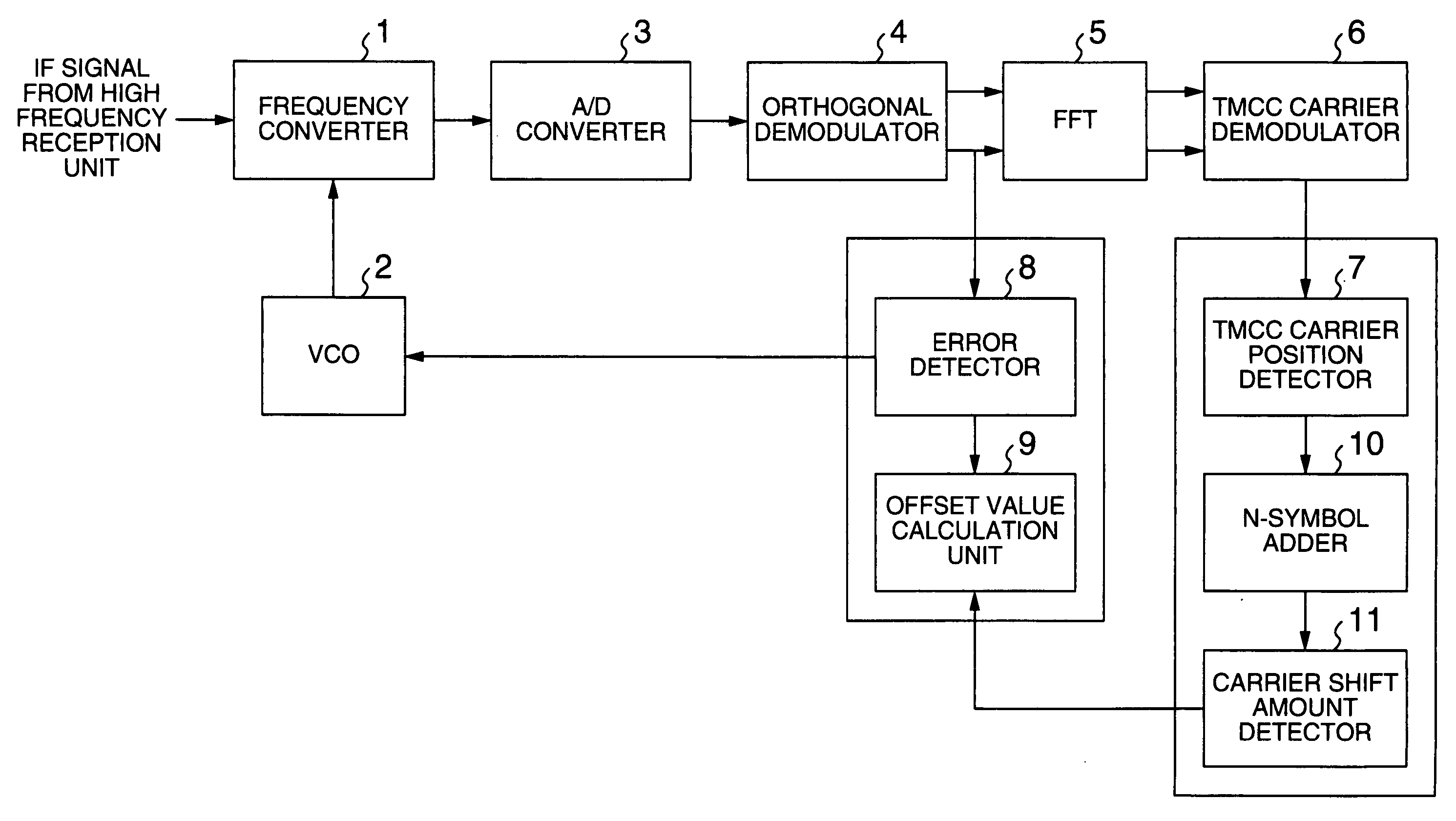
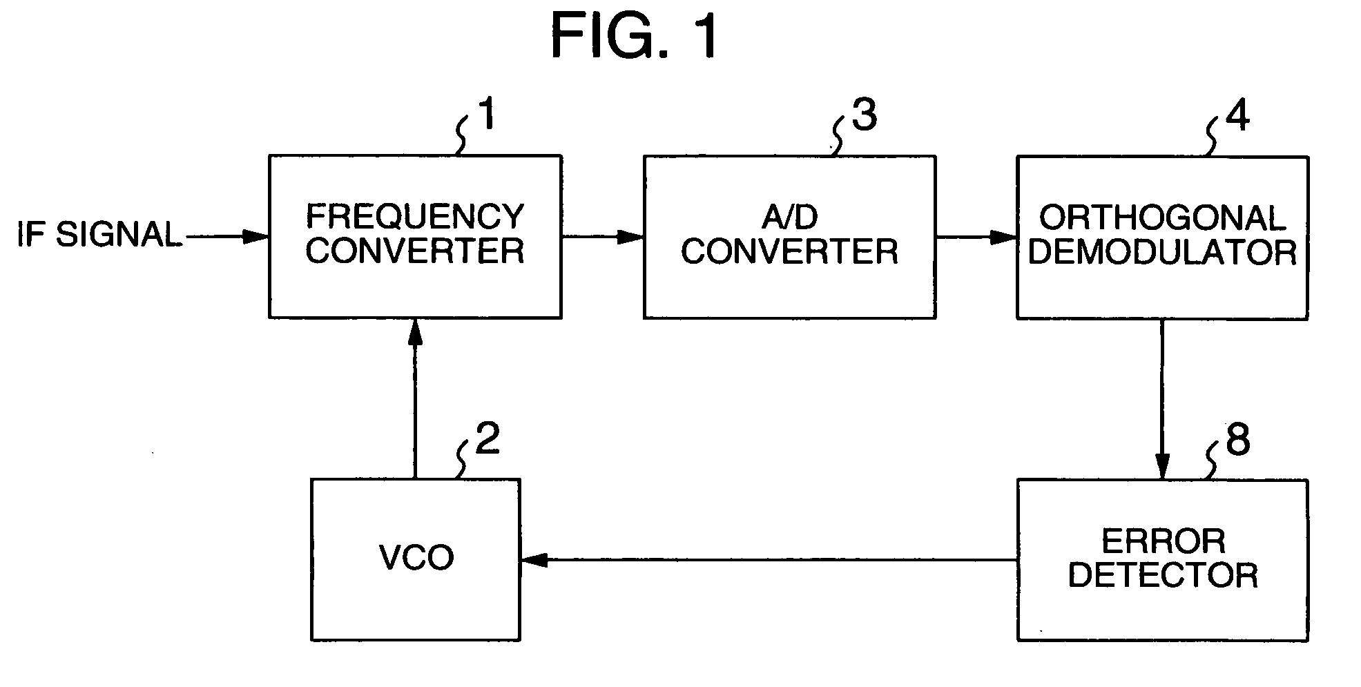
[0022] The present invention can be applied to a transmission system for transmitting a transmission signal which has main data carriers for sending main data, and sub-data carriers placed at random positions for sending sub-data. The main data used herein refers to such data as audio, video, and the like, and the sub-data refers to auxiliary data other than the main data, including, for example, mode identification data for modulation schemes and the like.

[0023] An example of such a transmission signal may be an OFDM transmission signal.

[0024] The following embodiment will be described in connection with an OFDM transmitter to which the present invention is applied.

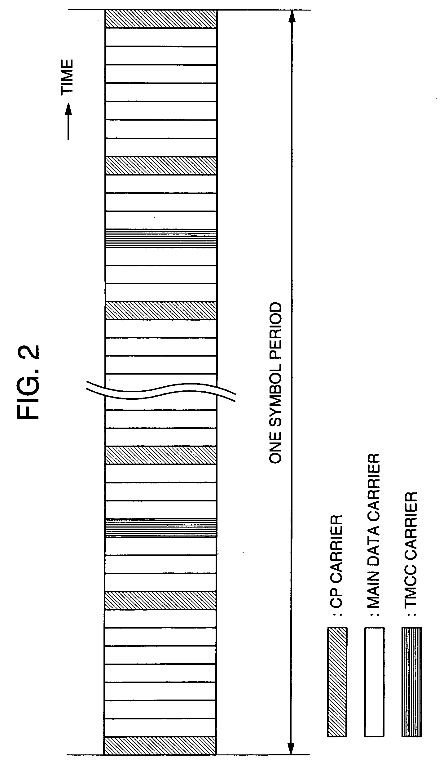
[0025] Before describing the present invention, a review will be made on the layout of carriers for use by the OFDM transmitter. As illustrated in FIG. 2, an OFDM transmission signal has a multi-carrier structure. Carriers are classified into a main data carrier for sending main data, and sub-data carriers placed at p...


PUM


Abstract

A TMCC carrier is demodulated from a received OFDM signal having a TMCC carrier. A relative carrier position of the demodulated TMCC carrier is detected. A carrier shift amount is detected from the detected relative carrier position of the TMCC carrier and a normal TMCC carrier position. The received OFDM signal is corrected for the carrier frequency shift based on the detected carrier shift amount.

Description

BACKGROUND OF THE INVENTION [0001] The present invention relates to improvements on immunity of a digital transmitter in transmission, and more particularly, to a method of detecting a carrier shift amount, a method of correcting the carrier shift amount, and a receiver employing these methods. [0002] In recent years, an orthogonal frequency division multiplex (hereinafter, abbreviated as “OFDM”) modulation scheme, which is characterized by immunity to multipath fading and ghost, has gain the spotlight because of its suitability to applications in mobile digital transmission and ground-based digital television broadcasting. [0003] The OFDM scheme, which is one of multi-carrier modulation schemes, digitally modulates n carriers (n ranges from several tens to several hundreds) which are orthogonal to one another. [0004] A transmission signal from a transmitter in such a digital communication system can suffer from shifts in frequency on a transmission path due to influences such as fa...

Claims


Application Information

Patent Timeline
IPC IPC(8): H04K1/10H04L27/26
CPCH04L27/2675H04L27/2657
Inventor TAKESUE, HIROYUKINAKADA, TATSUHIROTSUKAMOTO, NOBUO
Owner KOKUSA ELECTRIC CO LTD
Learn More