
Method of using a non-antibody protein to detect and measure an analyte

a non-antibody protein and analyte technology, applied in the field of diagnostics, can solve the problems of difficult to engineer antibody specificity, less accurate assay formats, and difficulty in generating two antibodies that differ in their site of binding to an analyte,

Inactive Publication Date: 2005-05-05
PROTOMETRIX
View PDF2 Cites 67 Cited by
  • Summary
  • Abstract
  • Description
  • Claims
  • Application Information

AI Technical Summary

Benefits of technology

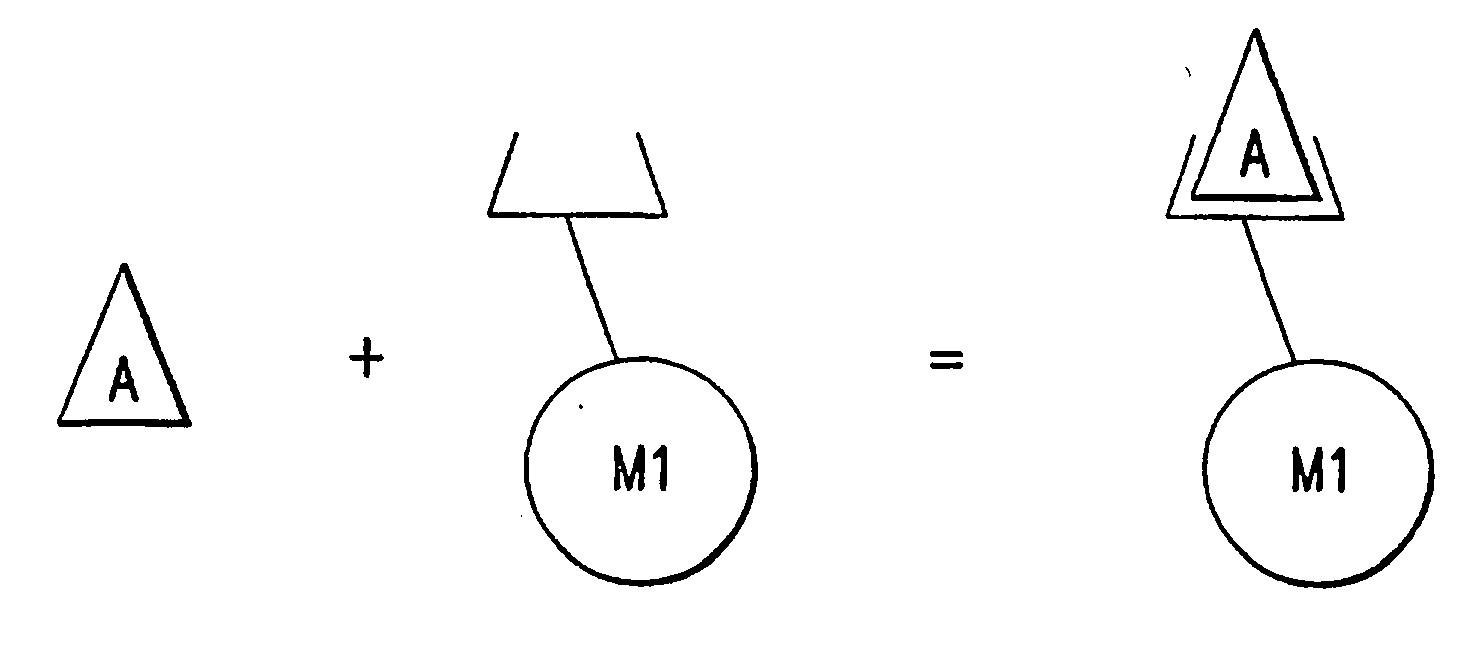
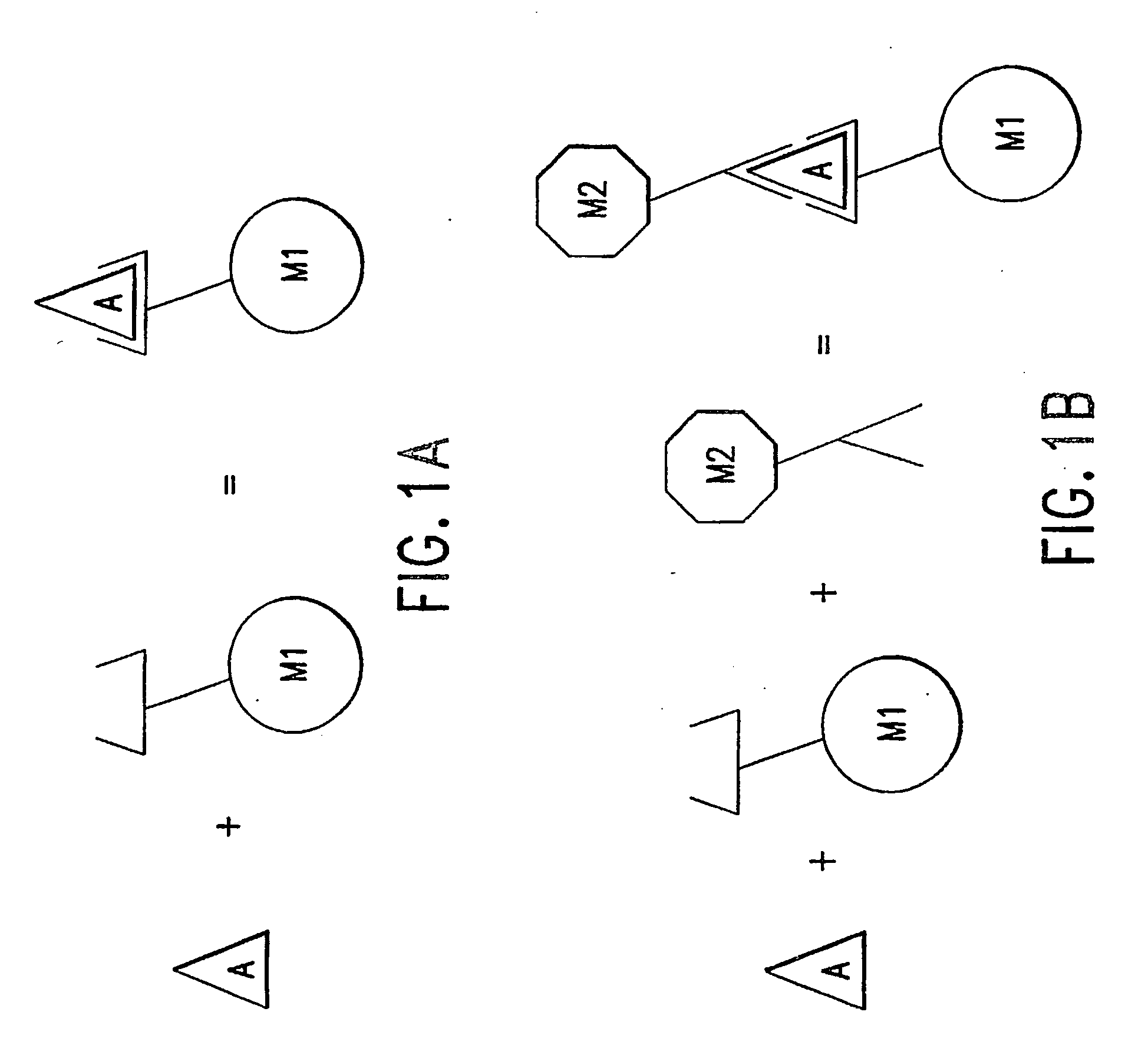
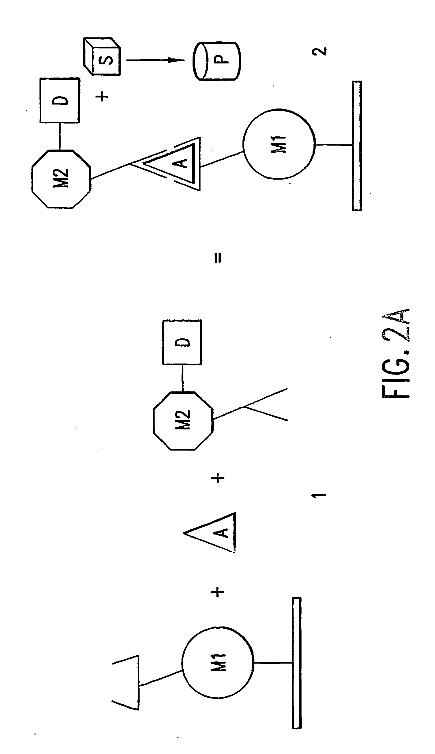
[0036] Therefore, a database of such interactions can be useful for designing a diagnostic assay. For example, a human-derived analyte can be screened against a collection of proteins derived from a non-human species, which collection has been tested in binding assays inter se to identify which proteins in the collection bind to each other protein in the collection (i.e., an interaction profile). Proteins from the collection which bind the analyte are identified, and reference to interaction profile identifies other proteins in the collection that can be used as second-level or third-level binding proteins. In this manner, a binding assay for the analyte of interest can be designed when one binding protein (that binds the analyte) in the collection of proteins is known. Usually, the binding protein that binds the analyte can identified by performing only one screening assay. Such methods of designing a diagnostic assay are advantageous because the methods reduce the need to test and identify necessary binding proteins empirically for each different assay.

Problems solved by technology

In the simplest of formats, the contact molecule and the reporter molecule can be on a single bimolecular molecule, but such assay formats tend to be less accurate than others in which more than one molecule is used in the detection process.
In general, antibody specificity is difficult to engineer and generating two antibodies that differ in their site of binding to an analyte can be even more difficult to achieve.
Supplies of such antibodies can be limited and production of the antibodies can be expensive and time-consuming.
Moreover, antibodies of sufficient specificity and affinity can be particularly difficult to obtain when the target analyte is weakly antigenic.
Obtaining two non-overlapping antibodies against weak antigens for sandwich assays is particularly challenging.

Method used


Image

  • Method of using a non-antibody protein to detect and measure an analyte
  • Method of using a non-antibody protein to detect and measure an analyte
  • Method of using a non-antibody protein to detect and measure an analyte

Examples


example 2

7. EXAMPLE 2

Detection of a Human Protein Analyte (RAS) Using a Yeast Proteome Microarray

[0260] A yeast proteome microarray containing nearly all yeast proteins was prepared and screened for a number of biochemical activities. A high-quality collection of 5800 yeast ORFs (93.5% of the total) was cloned into a yeast high-copy expression vector using Yeast 9:715). The yeast proteins were fused to GST-HisX6 at their amino termini and expressed in yeast under the control of a galactose-inducible GAL1 promoter (Zhu et al., 2000, Nature Genet. 26:283-289; Mitchell et al., 1993, 9(7):715-722). The yeast expression strains contain individual plasmids in which the correct yeast ORFs have been shown to be properly fused in-frame to GST by DNA sequencing.

7.1. Materials and Methods

[0261] Briefly, yeast ORFs were amplified by PCR and co-transformed into yeast cells along with the vector to generate expression clones. The plasmids were rescued in E. coli, and the vector-insert junctions were ...


PUM

PropertyMeasurementUnit
Fractionaaaaaaaaaa

Abstract

The present invention relates to diagnostics, particularly binding assays for detecting and / or measuring an analyte. The present invention relates to methods for determining the presence and / or amount of an analyte by means of association with one or more non-antibody molecules, in particular non-antibody molecules derived from a species different from that of the analyte. Further, the present invention relates to methods for diagnosing and staging diseases by detecting and / or measuring analytes associated with certain diseases.

Description

RELATED APPLICATIONS [0001] This application claims the benefit of application No. 60 / 331,706 filed Nov. 19, 2001, the entire disclosure of which is incorporated herein by reference in its entirety.1. FIELD OF TIE INVENTION [0002] The field of the invention is diagnostics, particularly binding assays for detecting and / or measuring an analyte. The present invention relates to methods for determining the presence and / or amount of an analyte by means of association with one or more non-antibody molecules, in particular molecules derived from a species different from that of the analyte. Further, the present invention relates to methods for diagnosing and staging diseases by detecting and / or measuring analytes associated with certain diseases. 2. BACKGROUND OF THE INVENTION [0003] Methods for detecting an analyte in vitro are well known in the art. In general, the detection process requires contact with the analyte and a measurable report (qualitative or quantitative) that contact with ...

Claims


Application Information

Patent Timeline
IPC IPC(8): A61BG01N33/53C12N1/00C12Q1/68G01N33/543G01N33/544G01N33/551G01N33/566G01N33/68G01N37/00
CPCG01N33/54306
Inventor SHERMAN, MICHAEL I
Owner PROTOMETRIX
Learn More