Cardiac imaging system and method for quantification of desynchrony of ventricles for biventricular pacing

a biventricular pacing and imaging system technology, applied in the field of cardiac rhythm management systems, can solve the problems of delayed left ventricular ejection, different regions of the left ventricle not contracting in a coordinated fashion, and ineffective contraction of the left ventricl

Active Publication Date: 2005-05-05
APN HEALTH +1
View PDF51 Cites 86 Cited by
  • Summary
  • Abstract
  • Description
  • Claims
  • Application Information

AI Technical Summary

Benefits of technology

[0010] In another aspect, a method for planning biventricular pacing lead placement for a patient includes obtaining cardiac acquisition data from a medical imaging system, and determining a movement profile from the cardiac acquisition data. The movement profile is directed toward identifying at least one of a time-based contraction parameter for a region of the left ventricle (LV), and a displacement-based contraction parameter for a region of the LV. The determined movement profile is visually displayed by generating a 3D model therefrom, and one or more coronary vessels are visualized on the generated 3D model. At least one suitable region is identified on the left ventricle wall for epicardial lead placement.
[0011] In still another aspect, a method for planning biventricular pacing lead placement for a patient includes obtaining cardiac acquisition data from a medical imaging system, and

Problems solved by technology

However, in those patients with CHF and LBBB, a long mechanical delay in the left side of the heart leads to a delayed left ventricular ejection due to delayed left ventricular depolarization.
In addition, this condition (also known as desynchrony) may also result in different regions of the left ventricle not contracting in a coordinated fashion.
Subsequently, the lateral wall then shortens and the septum stretches, thereby causing an ineffective contraction of the left ventricle.
However, in over 20% of these patients, lead placement in the CS may be unsuccessful or a very lengthy procedure, or the lead may become dislodged from the CS.
Other difficulties with this lead placement procedure may also include unavailability of a suitable CS branch, significant rotation of the CS due to left atrium and left ventricle dilation, and the presence of the Tebesian valve therein.
In most instances, these problems are identified only at the time of the interventional procedure, and thus the procedure

Method used


Image

  • Cardiac imaging system and method for quantification of desynchrony of ventricles for biventricular pacing
  • Cardiac imaging system and method for quantification of desynchrony of ventricles for biventricular pacing
  • Cardiac imaging system and method for quantification of desynchrony of ventricles for biventricular pacing

Examples


Embodiment Construction

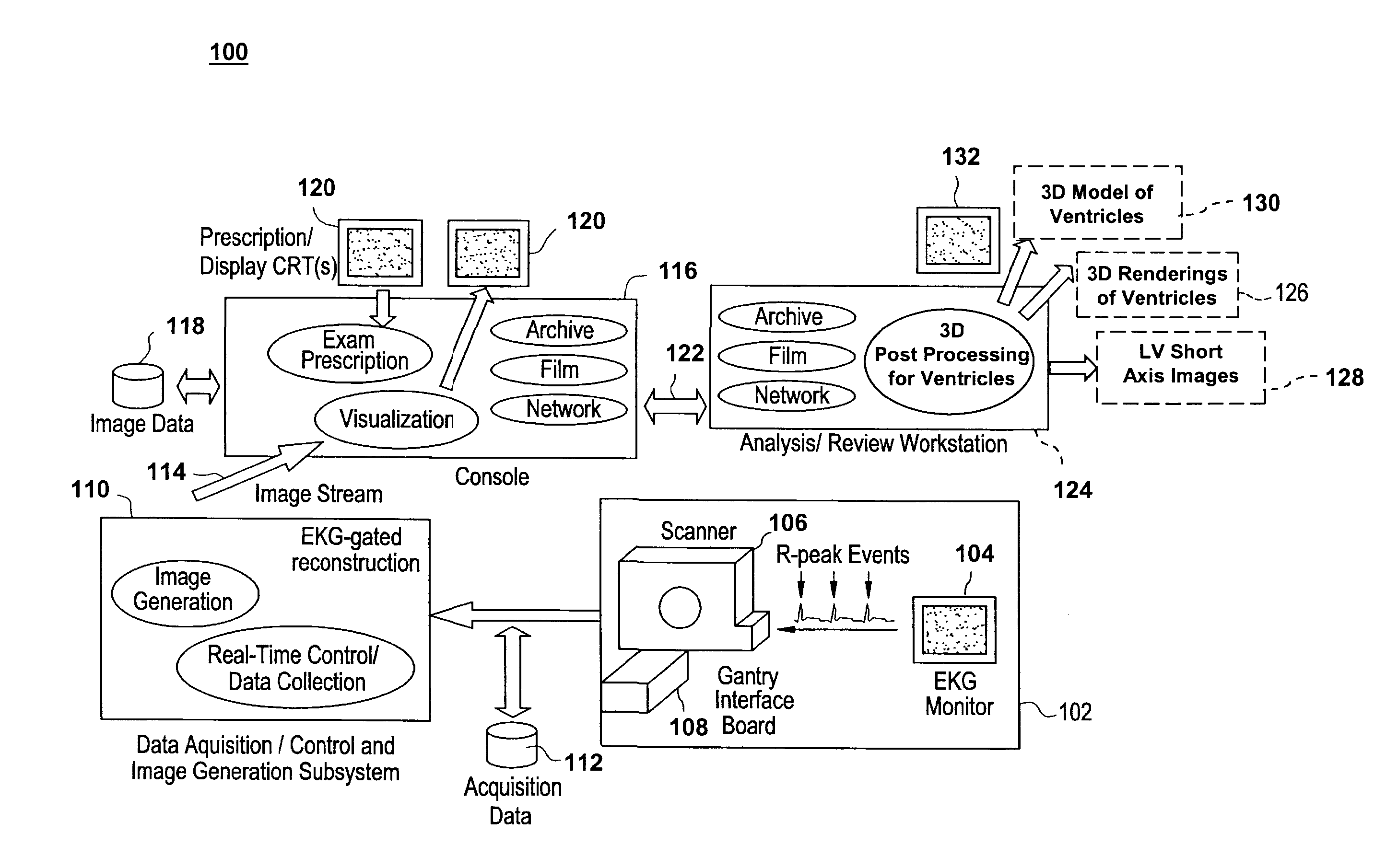
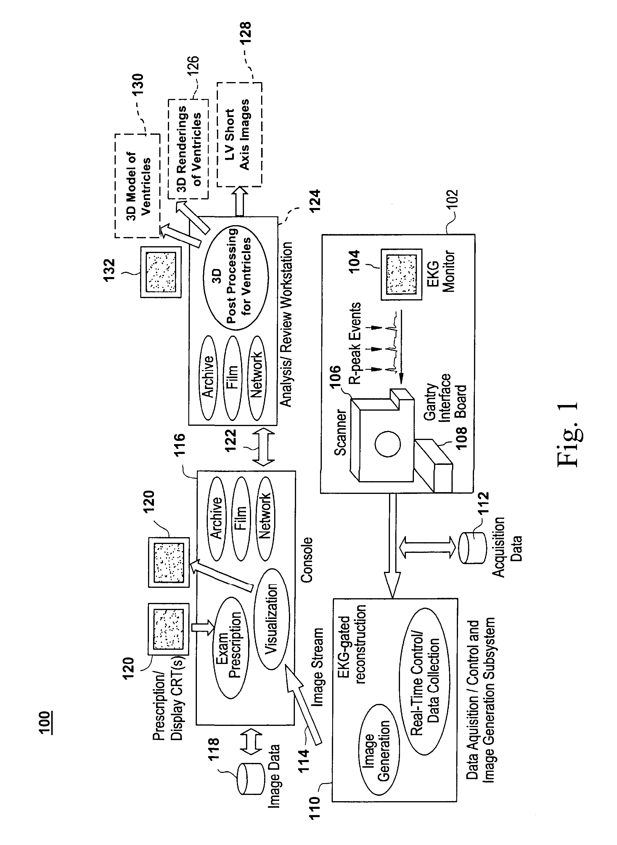
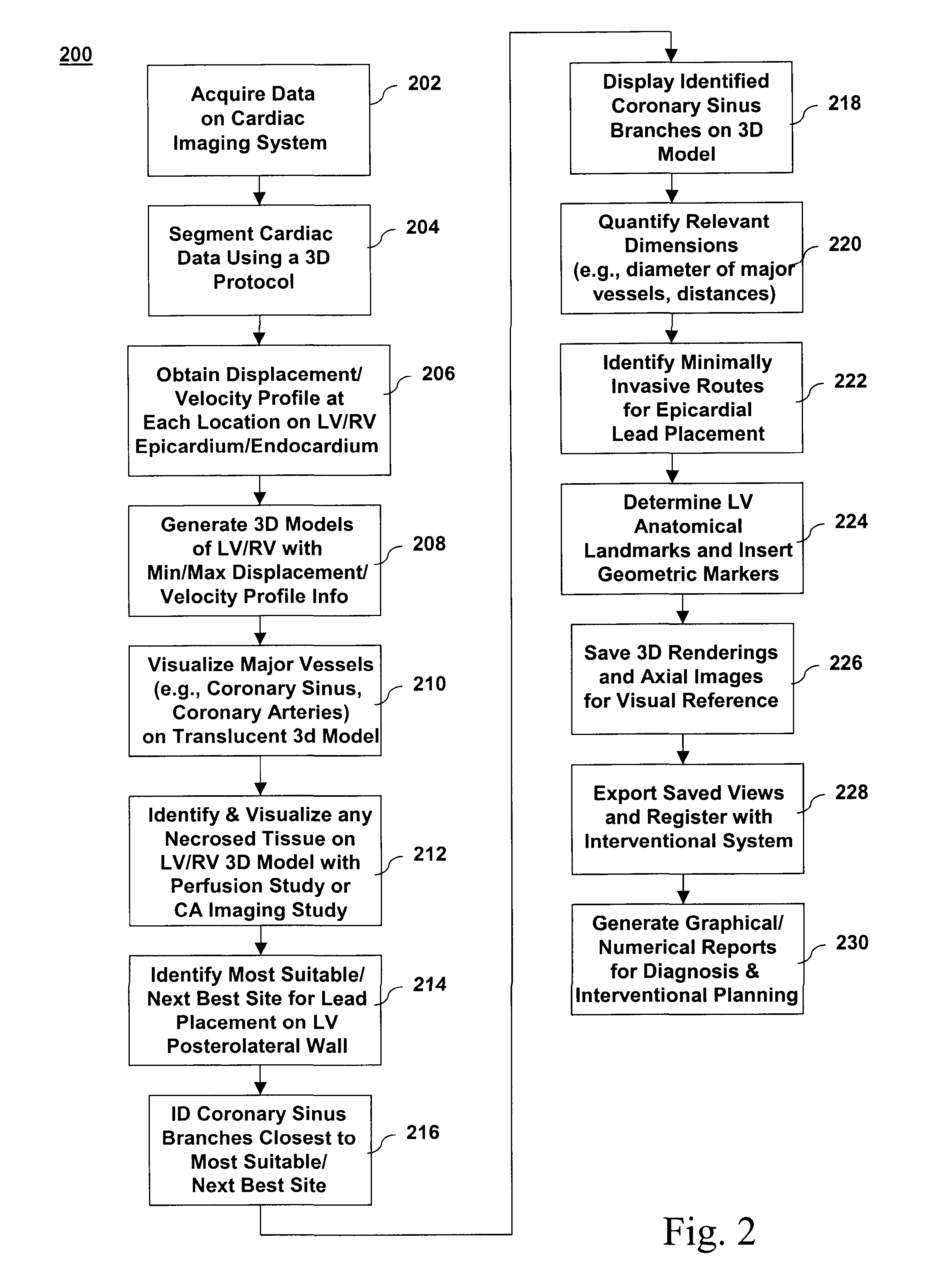
[0026] Disclosed herein is a cardiac imaging system and method for quantifying the desynchrony of the right and left ventricles so as to provide information for planning biventricular pacing interventional procedures enabling the practitioner (e.g., electrophysiologist, cardiologist, surgeon) to plan in advance the approach to take for the procedure. LV contractility can be visualized to identify the best location for placement of the LV epicardial pacing lead by, for example, determining the LV region that is the “last to contract” (i.e., a time-based contraction parameter). As used hereinafter, the term “last to contract” may be quantified as either last to start contraction or last to complete contraction by the exemplary method described in greater detail below. Alternatively, LV contractility can be visualized by determining the LV region that exhibits the most / least amount of displacement with respect to a starting position at a given point in the cardiac cycle (i.e., a displa...


PUM


Abstract

A method for quantifying cardiac desynchrony of the right and left ventricles includes obtaining cardiac acquisition data from a medical imaging system, and determining a movement profile from the cardiac acquisition data. The movement profile is directed toward identifying at least one of a time-based contraction parameter for a region of the left ventricle (LV), and a displacement-based contraction parameter for a region of the LV. The determined movement profile is visually displayed by generating a 3D model therefrom.

Description

BACKGROUND OF THE INVENTION [0001] The present disclosure relates generally to cardiac rhythm management systems and, more particularly, to a cardiac imaging system and method for quantification of desynchrony of ventricles for biventricular pacing. [0002] It is estimated that approximately 6-7 million people in the United States and Europe alone have congestive heart failure (CHF), with ischemic and idiopathic cardiomyopathies being the most common causes of CHF. In about 20-50% of patients having CHF, the associated electrocardiograms are characterized by prolonged PR intervals and wide QRS complexes. Moreover, about 29% of these patients have left bundle branch block (LBBB). [0003] In a normal heartbeat, the electrical conduction begins in the sinoatrial (SA) node (a small group of muscle cells in the upper right part of the upper right heart chamber, i.e., the right atrium). Impulses sent out by the SA node spread quickly throughout the upper heart chamber and across the atriove...

Claims


Application Information

Patent Timeline
IPC IPC(8): A61B6/00A61B6/03G06T7/00
CPCA61B5/7289A61B6/032A61B6/503A61B6/507A61B6/541G06T7/0012G06T2207/30048A61B6/504
Inventor REDDY, SHANKARA BONTHUFUNG, MAGGIE MEI-KEISRA, JASBIR S.OKERLUND, DARRIN R.PALMER, CHRISTINE MARY
Owner APN HEALTH
Why Eureka
Try Eureka