Methods for modeling, designing, and optimizing the performance of drilling tool assemblies

a technology for drilling tool assemblies and performance optimization, applied in the direction of waterlogging instruments, borehole/well accessories, etc., can solve the problems of large fluctuation in the wob, torsional, axial and lateral vibration of drilling tool assemblies, and the damping is typically not enough to suppress vibration completely, so as to achieve the effect of optimizing the performance parameter of drilling tool assemblies

Active Publication Date: 2005-05-05
SMITH INT INC
View PDF65 Cites 168 Cited by
  • Summary
  • Abstract
  • Description
  • Claims
  • Application Information

AI Technical Summary

Problems solved by technology

However, in most cases, the majority of the fluctuation in the WOB can be attributed to drilling tool assembly vibrations in the wellbore.
In general, drilling tool assemblies may experience torsional, axial and lateral vibrations.
Although partial damping of vibration may result due to viscosity of drilling fluid, friction of the drill string rubbing against the wall of the wellbore, energy absorbed in drilling the formation, and drilling tool assembly impacting with wellbore wall, these sources of damping are typically not enough to suppress vibrations completely.
Vibrations of a drilling tool assembly have been difficult to predict because different forces may combine to produce the various modes of vibration, and models for simulating the response of an entire drilling tool assembly including a drill bit interacting with formation in a drilling environment have not been available.
Drilling tool assembly vibrations are generally undesirable, not only because they are difficult to predict, but also because they can significantly affect the instantaneous force applied on the bit.
This can result in the bit not operating as expected.
For example, vibrations can result in off-centered drilling, lack of control in the direction of drilling, slower rates of penetration, excessive wear of the cutting elements, or premature failure of the cutting elements and the bit.
Lateral vibration of the drilling tool assembly may be a result of radial force imbalances, mass imbalance, and bit / formation interaction, among other things.
Lateral vibration results in poor drilling tool assembly performance, overgage hole drilling, out-of-round, or “lobed” wellbores and premature failure of both the cutting elements and bit bearings.
Because a drilling tool assembly may extend for more than a mile, pipe trips can take several hours and can pose a significant expense to the wellbore operator and drilling budget.
However, no prior art simulation techniques have been developed to cover the dynamic modeling of an entire drilling tool assembly which includes the simulated interaction of the drill bit with the bottomhole surface, until the development of methods disclosed in U.S. patent application Ser. No. 09 / 689,299, filed Oct. 11, 2000 and incorporated herein by reference.
Prior to this disclosure, the dynamic response of a drilling tool assembly or the effect of a change in configuration on drilling tool assembly performance could not be accurately predicted.
Thus, numerous sensors, measurement devices, and control systems were employed in drilling to determine a more accurate prediction of the drilling response of a given drilling tool assembly, which significantly added to the overall cost of drilling the well.
Because previous simulation methods do not take into account the dynamic response of the entire drilling tool assembly to the calculated interaction of cutting elements with earth formation during drilling, accurately predicting the response of a given drilling tool assembly in drilling a particular formation was virtually impossible.
Additionally, the change in the dynamic response of a drilling tool assembly when a component of the drilling tool assembly was changed was not well understood.

Method used


Image

  • Methods for modeling, designing, and optimizing the performance of drilling tool assemblies
  • Methods for modeling, designing, and optimizing the performance of drilling tool assemblies
  • Methods for modeling, designing, and optimizing the performance of drilling tool assemblies

Examples


Embodiment Construction

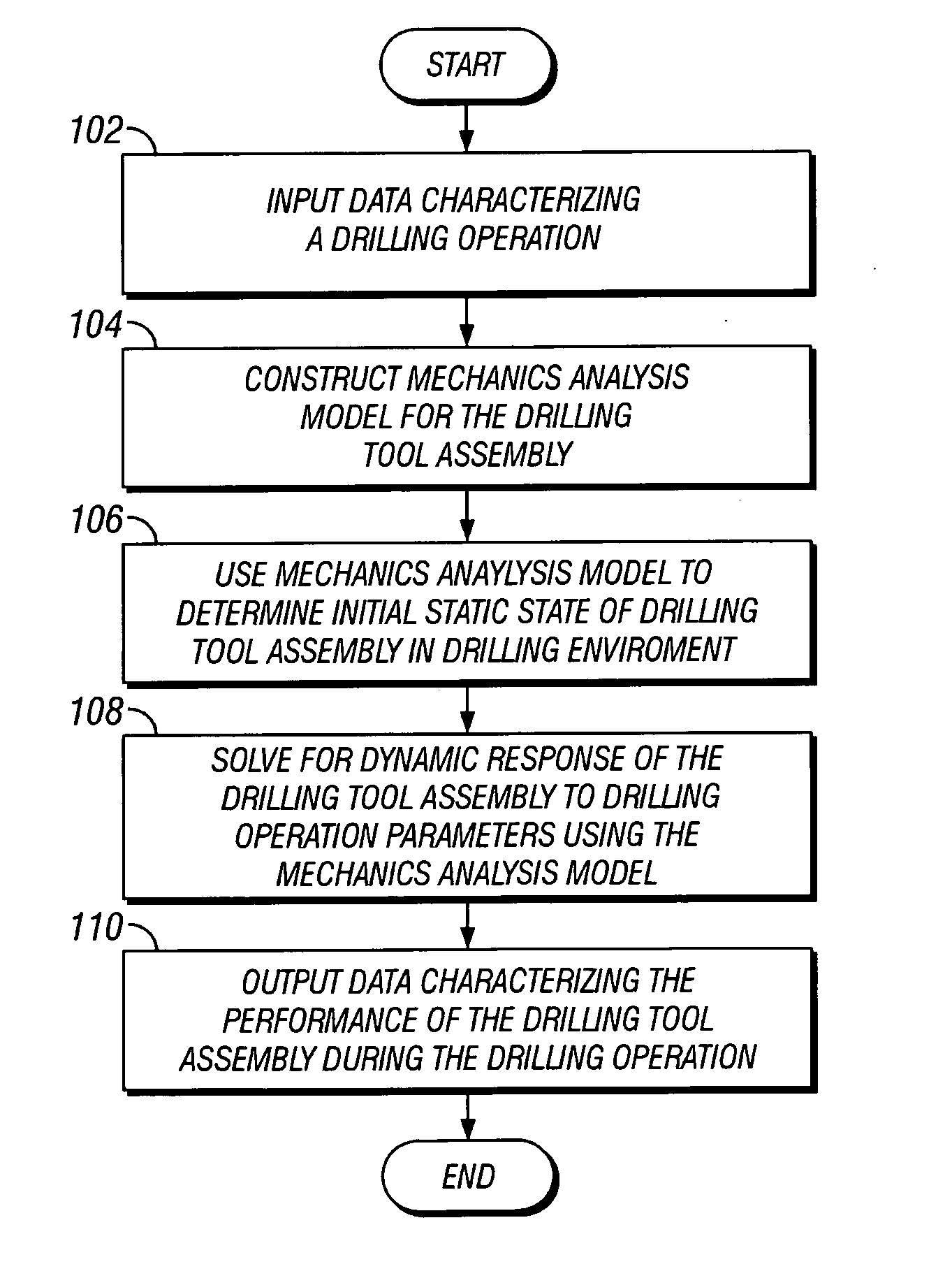
[0051] The present invention provides methods for predicting the dynamic response of a drilling tool assembly drilling an earth formation, methods for optimizing a drilling tool assembly design, methods for optimizing drilling operation parameters, and methods for optimizing drilling tool assembly performance.

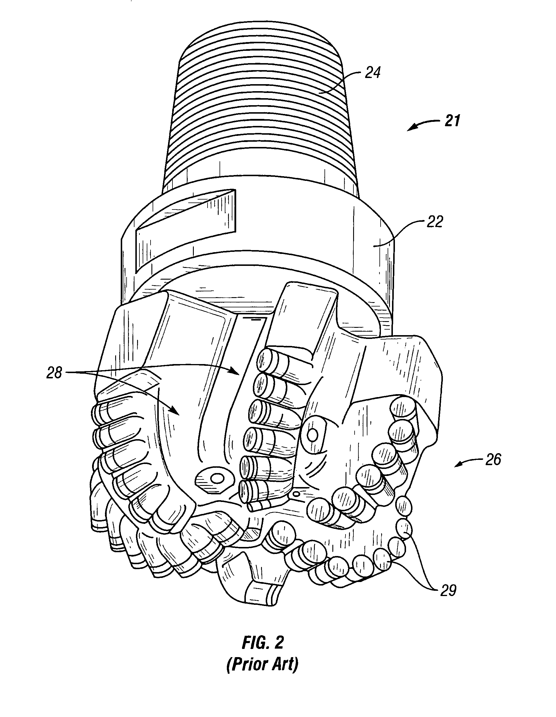
[0052] Methods for determining the dynamic response of a drilling tool assembly to drilling interaction with an earth formation were initially disclosed in U.S. patent application Ser. No. 09 / 689,299 by Huang, which is assigned to the assignee of the present invention and incorporated herein by reference. New methods developed for modeling fixed cutter drill bits are disclosed in U.S. Patent Application No. 60 / 485,642 by Huang, filed on Jul. 9, 2003, titled “Method for Modeling, Designing, and Optimizing Fixed Cutter Bits,” assigned to the assignee of the present application and incorporated herein by reference in its entirety. Methods disclosed in the '642 application may adv...


PUM


Abstract

A method for designing a drilling tool assembly, having a drill bit disposed at one end includes defining initial drilling tool assembly design parameters; calculating a dynamic response of the drilling tool assembly; adjusting a value of a drilling tool assembly design parameter; and repeating the calculating and the adjusting until a drilling tool assembly performance parameter is optimized.

Description

CROSS-REFERENCE TO RELATED APPLICATIONS [0001] This application claims the benefit under 35 U.S.C. § 120 as a continuation-in-part of U.S. application Ser. No. 09 / 689,299, filed Oct. 11, 2000 and titled “Simulating the Dynamic Response of a Drilling Tool Assembly and Its Application to Drilling Tool Assembly Design Optimization and Drilling Performance Optimization,” which is incorporated herein by reference in its entirety. This application also claims the benefit under 35 U.S.C. §119(e) of U.S. Provisional Application No. 60 / 485,642, filed Jul. 9, 2003 and titled “Methods for Modeling, Designing, and Optimizing Fixed Cutter Bits,” which is also incorporated herein by reference in its entirety.[0002] Further, U.S. patent application entitled “Methods For Modeling, Displaying, Designing, And Optimizing Fixed Cutter Bits,” filed on Jul. 9, 2004, U.S. patent application entitled “Methods for Designing Fixed Cutter Bits and Bits Made Using Such Methods,” filed on Jul. 9, 2004, and U.S....

Claims


Application Information

Patent Timeline
Patent Type & Authority Applications(United States)
IPC IPC(8): E21B10/16E21B41/00G01V1/40
CPCE21B44/00E21B10/16
Inventor HUANG, SUJIAN
Owner SMITH INT INC
Why Eureka
Try Eureka