Antiglare device for welding protective masks

a technology of antiglare and protective mask, which is applied in the direction of eye masks, photometry, garments, etc., can solve the problems of affecting the safety of welding equipment, so as to improve the safety of protection equipment, reduce the risk of interference, and reduce the risk of welding equipment damag

Inactive Publication Date: 2005-05-12
OPTREL AG
View PDF14 Cites 14 Cited by
  • Summary
  • Abstract
  • Description
  • Claims
  • Application Information

AI Technical Summary

Benefits of technology

[0006] It is an objective of the present invention to create a glare protection device, which overcomes these disadvantages prevailing up until now, which is less sensitive against the effects of extraneous light, and which makes possible a more simple, better and safer controlling of the protective filters without any malfunction.
[0007] In accordance with the invention the glare protection device incorporates an optical sensor that is a UV-detector having a sensor evaluation circuit that generates a signal for controlling of the protective filter and which corresponds to the UV intensity. With the optical sensor designed as a UV-detector, directly and to a great extent, the actual welding light is detected, while in correspondence with the relatively smaller UV proportion of extraneous light and stray light effects their influence is small. With the detection and evaluation of the measured UV intensity by a corresponding evaluation circuit, for the controlling of the protective filter a relatively simple, insensitive, and safe against interfering influences switching of the protective filter is achieved.
[0008] In particular, with the device and method according to the present invention a more simple, safer, and better electronic circuit for the controlling of the protective filters is able to be utilised. Thus, it is possible to make do without an elaborate and very sensitive flickering light detection—and evaluation in the electronic circuit.
[0009] The present invention further provides benefits with respect to simplicity, operational safety, optimum adjustability of the blacking out and universal usability as well as additional advantages in the handling of glare protection devices of this kind. A particularly advantageous embodiment of the UV-detector may comprise a fluorescent layer in combination with a Si-sensor.

Problems solved by technology

For this reason, within the sensitivity range of the silicon detectors utilised up to now a relatively small proportion of the welding light and in contrast, however, a great proportion of extraneous—and stray light is detected, which renders the differentiation of the welding light from this stray light exceedingly difficult.
In the case of an insufficient differentiation of the welding light from the extraneous light a malfunction occurs, i.e., that the blacking out does not switch on when welding light occurs, because the extraneous light sources are dominant.
Similarly, insufficient differentiation also may prevent the blacking out from being switched off when the welding light ceases.
The signal to noise ration here, however, is very poor, so that flickering light circuits of this type are exceedingly sensitive, elaborate, and subject to interferences.

Method used


Image

  • Antiglare device for welding protective masks
  • Antiglare device for welding protective masks
  • Antiglare device for welding protective masks

Examples


Embodiment Construction

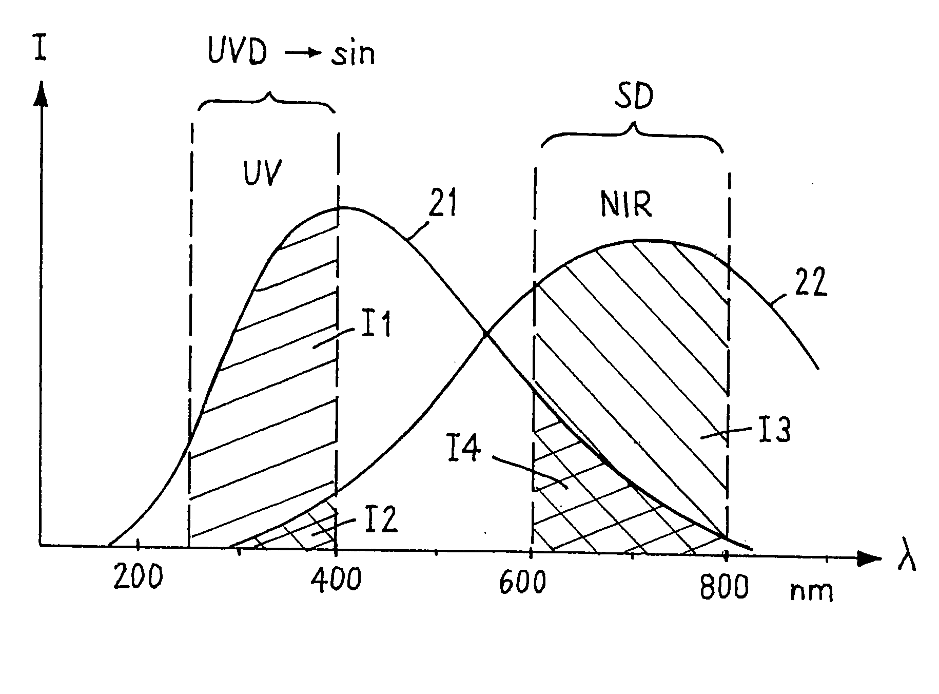
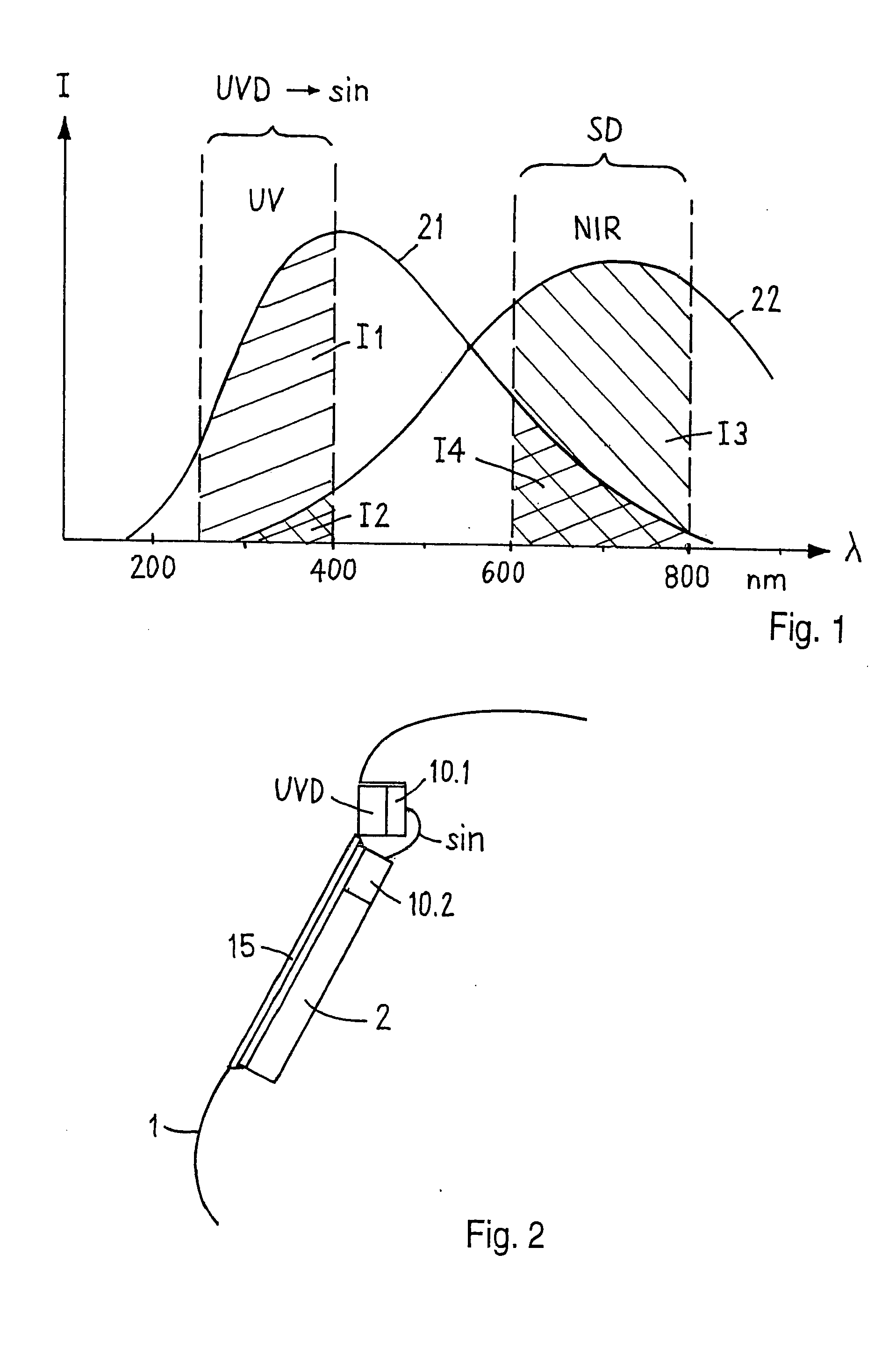
[0017]FIG. 1 schematically illustrates the spectral intensity distributions I(λ) for a welding light 21 with a high intensity proportion in the short-wave range and for an artificial light source as extraneous light 22 with a high proportion in the long-wave range. The welding light comprises a high intensity proportion I1 in the UV range, which is detected by a UV-detector UVD. The artificial light in contrast comprises a high intensity proportion I3 in the red range NIR, which is detected by a conventional Si-photo sensor SD. In the UV range the artificial light 22 comprises a small intensity proportion I2, while vice-versa the welding light 21 comprises a small intensity proportion I4 in the NIR range.

[0018] The UV-detector UVD, e.g., detects a short-wave range of 250-400 nm and the Si-photo detector SD a long-wave range of, e.g., 600-900 nm. With Si-sensors SD used up to now, therefore a relatively poor intensity ration I4 / I3 of welding light to extraneous light is detected, wh...


PUM

PropertyMeasurementUnit
wave-lengthaaaaaaaaaa

Abstract

A glare protection device for a welding protective mask includes active electro-optical protective filter (2) and an electronic circuit (10). A UV-detector (UVD), which serves as an optical sensor, detects the welding light and, via an evaluation circuit (10.1), generates a signal (sin) for controlling of the protective filter (2). The signal corresponds to the detected UV intensity. This results in a simple and safe controlling of the protective filter, which is uninfluenced by the effects of extraneous light.

Description

BACKGROUND OF THE INVENTION [0001] The present invention is generally related to a glare protection device for welding protective masks and to a method for controlling a glare protection device. The present invention is further directed toward a glare protection device including an active electro-optical protective filter, an electronic circuit, and an optical sensor, and toward a method for controlling such a glare protection device. [0002] Glare protection devices of the aforementioned type are generally known from, for example, WO98 / 57606 or the EP 0 550 384, wherein an optical sensor for the detection of the welding light by means of an active electronic circuit switches an active electro-optical protective filter such that, when welding light occurs, immediately a predefined blacking out level (protection level) is switched on. Similarly, when the welding light stops, the blacking out is immediately switched off again. [0003] Modern glare protection devices of this kind, in par...

Claims


Application Information

Patent Timeline
Patent Type & Authority Applications(United States)
IPC IPC(8): A61F9/06G02F1/133
CPCG02F1/13318A61F9/067
Inventor ACKERMANN, EMIL
Owner OPTREL AG
Why Eureka
Try Eureka