
Electric vacuum cleaner

Inactive Publication Date: 2005-05-12
TOSHIBA TEC KK
View PDF2 Cites 17 Cited by
  • Summary
  • Abstract
  • Description
  • Claims
  • Application Information

AI Technical Summary

Benefits of technology

[0015] Accordingly, an object of the present invention is to provide an electric vacuum cleaner equipped with a step-up converter circuit with a DC power supply as a drive source, wherein the step-up converter circuit is operated with satisfactory efficiency based on the state of a load on the electric vacuum cleaner to thereby enhance dust suction performance of the electric vacuum cleaner and lengthen the usage time of a battery per charge.
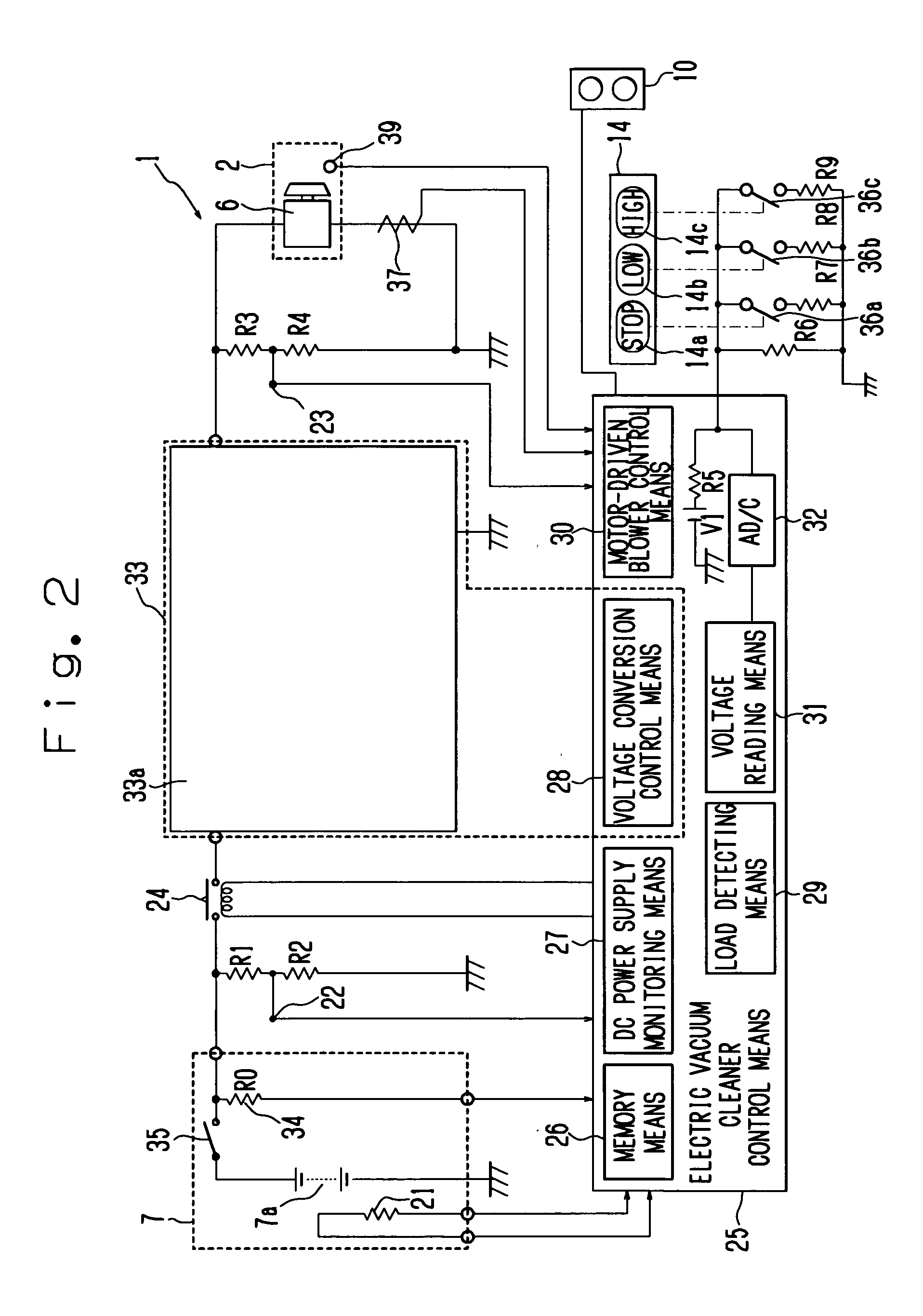
[0017] Thus, according to the novel electric vacuum cleaner of the present invention, such an electric vacuum cleaner equipped with a step-up converter circuit with a DC power supply as a drive source drives and controls the step-up converter circuit so as to refer to such a relationship inputted in advance to a memory means as to decrease a variation in dust suction capability, determine an output voltage to be boosted according to the state of a load on a motor-driven blower, boost the output voltage, based on the result of determination and supply power to the motor-driven blower, thereby activating the step-up converter circuit with satisfactory efficiency.

Problems solved by technology

When an attempt is made to increase an input current where the motor-driven blower is made up of a commutator motor, a carbon of a brush portion that makes contact with a commutator is worn, and the brush portion becomes apt to be damaged due to sparks or the like at the commutator.
It is therefore hard to ensure reliability.
However, in a case of requiring a high voltage, when only the batteries are used, each of the batteries becomes large-sized.
It is known that the electric vacuum cleaner equipped with the step-up converter circuit has a drawback that in a voltage boosting or step-up process at the operation of the step-up converter circuit, a power loss occurs due to a switching element or the like of a booster or step-up circuit.
Thus, the present technology does not disclose the state of a load and the operation of the step-up converter circuit.

Method used


Image

  • Electric vacuum cleaner
  • Electric vacuum cleaner
  • Electric vacuum cleaner

Examples


Embodiment Construction

[0036] A first embodiment of the present invention will be described with reference to FIGS. 1 through 17.

[External Configuration]

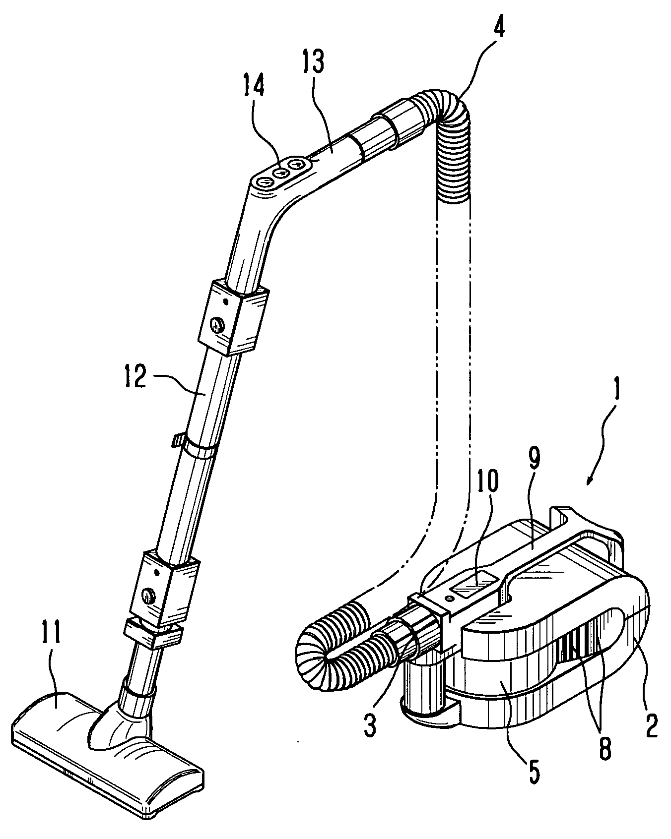
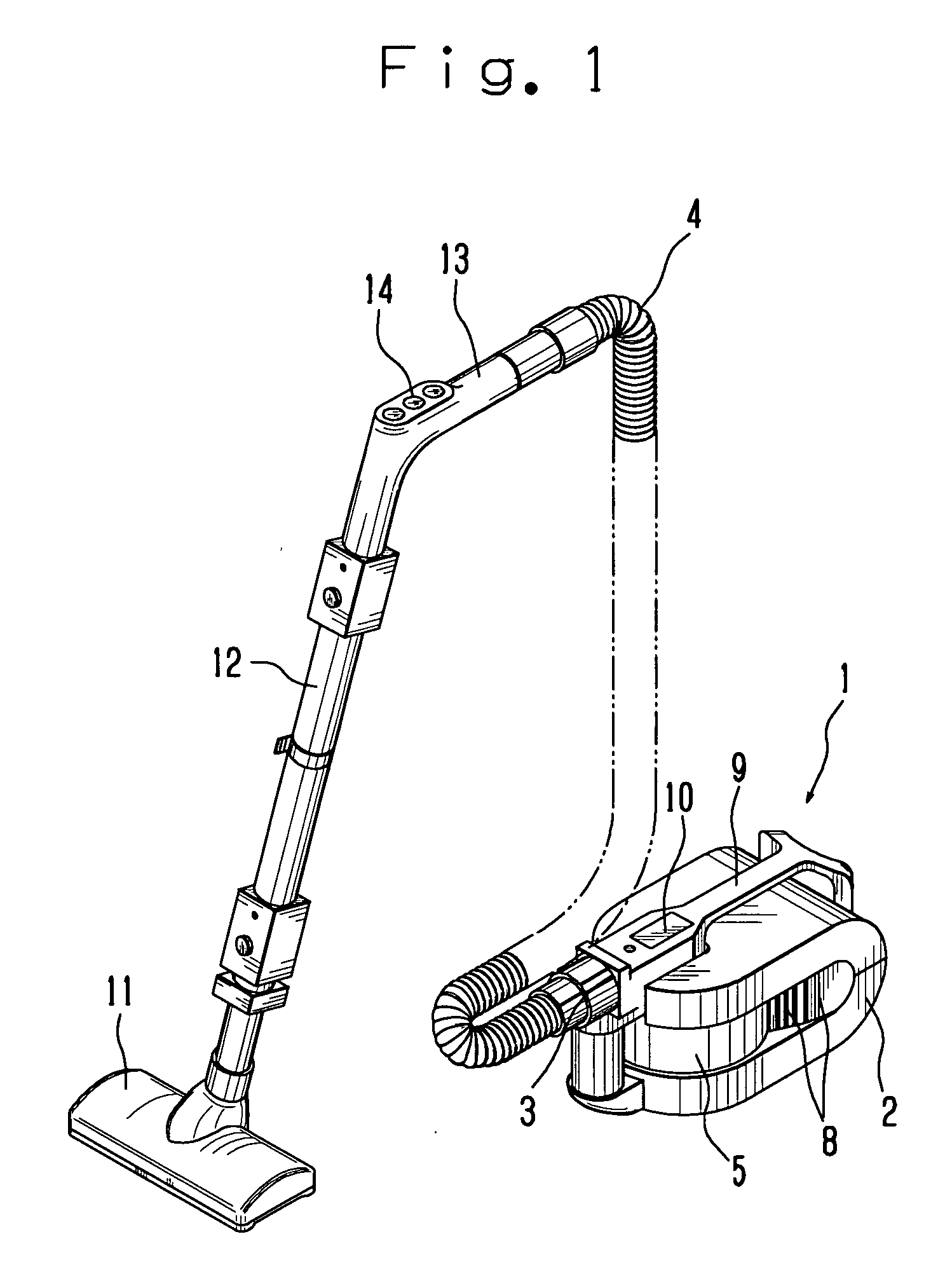
[0037]FIG. 1 is a perspective view showing an external configuration of an electric vacuum cleaner according to the embodiment of the present invention. As shown in FIG. 1, the electric vacuum cleaner 1 according to the present embodiment includes a hose body 4 detachably mounted to an inlet 3 attached to a case 2.

[0038] A dust cup 5 used as a dust chamber, a motor-driven blower 6, and a DC power supply (see FIG. 2) are provided within the case 2. A plurality of exhaust ports 8, which communicate with the motor-driven blower 6 and are open in substantially front side directions, are defined in side plate portions of the case 2. A handle 9 used as a knob means is provided on its corresponding upper surface of the case 2. The handle 9 is formed so as to take a substantially Y-shape as seen in a plane surface. A display means 10 provided with a plurality ...


PUM


Abstract

The present invention provides an electric vacuum cleaner equipped with a step-up converter circuit with a DC power supply as a drive source, which drives and controls the step-up converter circuit so as to refer to such a relationship as to decrease a variation in dust suction capability, determine an output voltage to be boosted according to the state of a load on a motor-driven blower, boost the output voltage, based on the result of determination and supply power to the motor-driven blower, thereby activating the step-up converter circuit with satisfactory efficiency. Thus, the dust suction performance of the electric vacuum cleaner is enhanced and the usage time of a battery per charge is lengthened.

Description

CROSS REFERENCE TO RELATED APPLICATION [0001] The present application is based on Japanese Priority Document JP2002-302682 filed on Oct. 17, 2003, the content of which is incorporated herein by reference. BACKGROUND OF THE INVENTION [0002] 1. Field of the Invention [0003] The present invention relates to an electric vacuum cleaner, and particularly to a battery-operated electric vacuum cleaner. [0004] 2. Discussion of the Background [0005] In a battery-operated electric vacuum cleaner provided with a motor-driven blower, a method for increasing an input to the motor-driven blower is generally known as a method for increasing the output of the motor-driven blower to enhance dust suction capability. As a specific example, there is known a method for changing windings of a motor-driven blower, increasing current inputted to the motor-driven blower, and boosting or stepping up a power supply voltage to thereby increase an input to the motor-driven blower. [0006] When an attempt is made ...

Claims


Application Information

Patent Timeline
IPC IPC(8): A47L9/28H02P7/292
CPCA47L9/2821A47L9/2831A47L9/2884A47L9/2857A47L9/2842
Inventor KUSHIDA, HIROYUKISAKURAI, OSAMU
Owner TOSHIBA TEC KK
Learn More