Locking unit

a technology of locking unit and locking plate, which is applied in the direction of gearing control, vibration dampers, brake systems, etc., can solve the problems of obstructing the movement of balls, unable to manufacture, and unable to guarantee the function of locking unit. achieve the effect of easy manufacturing

Inactive Publication Date: 2005-05-12
SVM SCHULTZ VERW
View PDF8 Cites 33 Cited by
  • Summary
  • Abstract
  • Description
  • Claims
  • Application Information

AI Technical Summary

Benefits of technology

[0010] Referring to this state of the art it is an object of the invention to improve a lockin

Problems solved by technology

With automatic transmissions, however, this is not possible because there is no frictional connection with the driven wheels when the engine has been turned off.
The use of the balls as operating elements, however, leads to some disadvantages.
Therefore it cannot be excluded completely that, for example, rubbed-of parts of the gear or other soiling (for example chips) are being deposited into the locking region and thus obstruct the movement of the balls.
If,

Method used


Image

  • Locking unit
  • Locking unit
  • Locking unit

Examples


Embodiment Construction

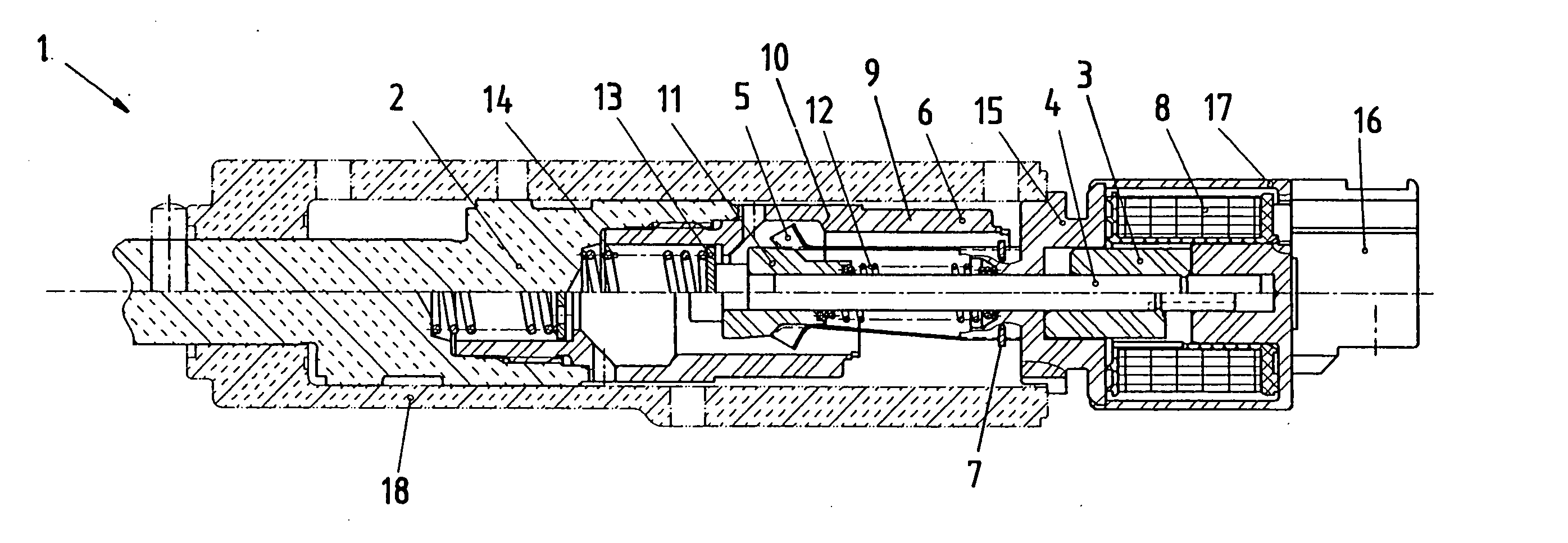
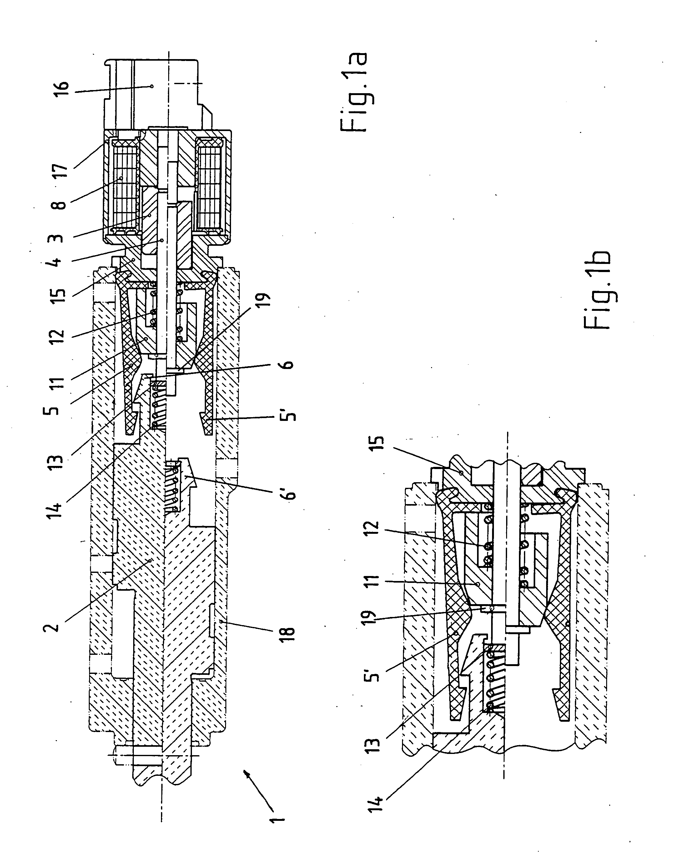
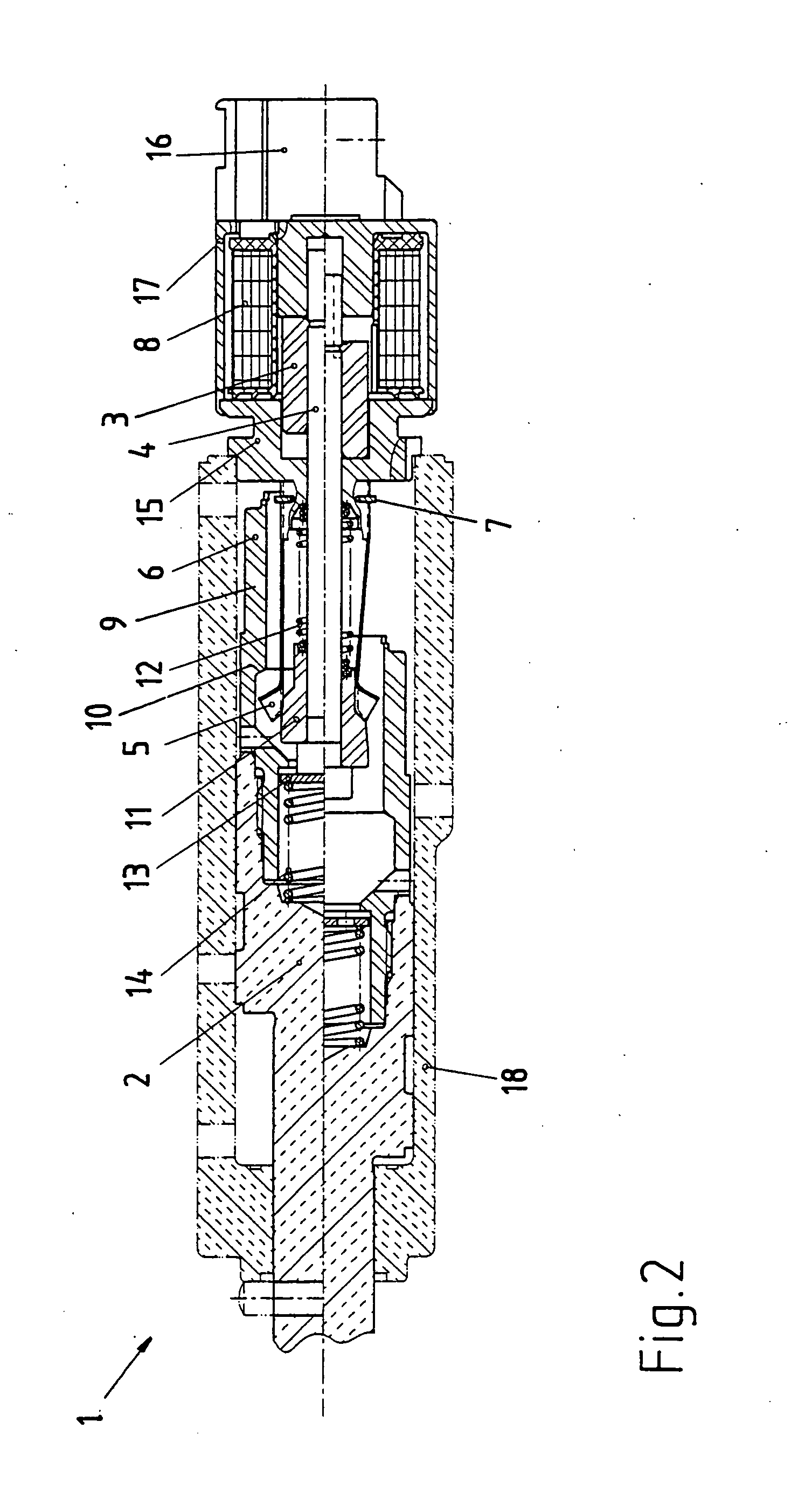
[0043] The locking unit 1 according to the invention comprises a piston 2 which can move longitudinally in a housing 18. By means of several borings there is a corresponding pressure of hydraulic oil, for example at the backside of the piston.

[0044] In all figures two positions each are shown. In each upper part of the figure the locking position is shown, in each lower part of the figure the unlocking position.

[0045] On the right hand side in FIG. 1a, respectively 2, the electromagnet is located. The connecting region is covered by the cap 16. The electromagnet is formed essentially by the coil 8 through the current flows in order to activate the electromagnet, as well as an armature 3, respectively an armature bar 4 connected with the armature 3.

[0046] In the upper part of the figure the armature 3 is attracted by the electromagnet, in the lower part of the figure there is a corresponding gap which occurs because of the spring 12 which tries to move the armature bar to the left...


PUM


Abstract

A locking unit for the locking of the movement of a piston. An electromagnet is provided the armature, respectively the armature bar, of which acts on an operating element. The operating element co-operates with a catching element in such a way that the catching element blocks in a locking position the movement of the piston, respectively the catching element unlocks in an unlocking position the movement of the piston. Catching element and operating element co-operate surface-to-surface.

Description

[0001] The invention refers to a locking unit for the locking of the movement of a piston which can be impinged with pressure, an electromagnet being provided the armature, respectively the armature bar, of which acting directly or indirectly on an operating element which co-operates with a catching element in such a way that the catching element blocks in a locking position the movement of the piston, respectively the catching element unlocks in an unlocking position the movement of the piston. BACKGROUND OF THE INVENTION [0002] Locking units described above are used in particular with the parking brakes in automatic transmissions. [0003] A vehicle with manual gear shifting can be secured against unintended movement during standstill when the engine has been turned off by engaging a gear. With automatic transmissions, however, this is not possible because there is no frictional connection with the driven wheels when the engine has been turned off. Therefore automatic transmissions ...

Claims


Application Information

Patent Timeline
IPC IPC(8): F16H63/34F16H63/48
CPCF16H63/3475F16H63/3433
Inventor KLEINERT, DIETERSCHERER, GEORGWILLBURGER, WINFRIEDMUELLER, ROBERT
Owner SVM SCHULTZ VERW
Why Eureka
Try Eureka