
System and method for warm air space heating with electrical power generation

a technology of electrical power generation and warm air space, which is applied in the direction of lighting and heating apparatus, machine/engine, heating type, etc., can solve the problems of large fraction of fuel energy normally dispersed as waste heat, no widespread use of small-scale cogeneration, and little attention to how such small-scale power generation technologies are applied

Active Publication Date: 2005-05-12
CLIMATE ENERGY
View PDF15 Cites 54 Cited by
  • Summary
  • Abstract
  • Description
  • Claims
  • Application Information

AI Technical Summary

Benefits of technology

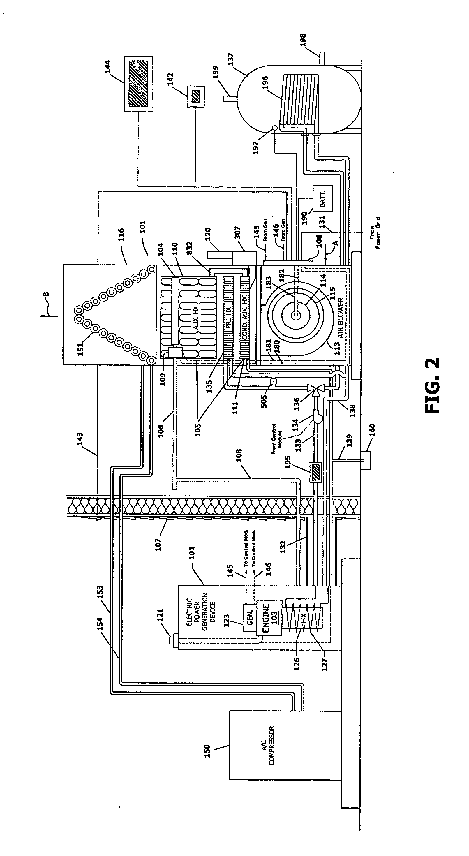
[0012] To provide a more-even and immediately plentiful supply of heat, an intermediate buffer tank is heated by the generator's heat and the heated liquid in the buffer tank can be directed to the heating unit and domestic water supply to supply their needs. Likewise, the primary heat exchanger can receive heated coolant from both the generator and an auxiliary liquid heater on a common circuit, eliminating the need for multiple heat exchangers in the cabinet.

Problems solved by technology

All forms of electric power generation at large remotely located generating plants result in a large fraction of the fuel energy being normally dissipated as waste heat.
However, there is as yet no widespread use of small-scale cogeneration.
To date, little attention has been paid to specifically how such small-scale power generation technologies would be practically integrated into central forced warm air heating furnaces and systems.
Also, nearly all candidate generator technologies suitable for use in small-scale cogeneration of electric power and heat incorporate a liquid cooling (for example, glycol, water, and mixtures thereof) circuit and are not practically or conveniently implemented with direct air cooling of the key function components.
A small scale cogeneration design that is a simple additive combination of warm air heating units of conventional design with available liquid cooled electric power generation devices is neither mechanically or electrically practical and will lead to inefficient and expensive systems.
While attempts to produce a small-scale cogeneration system have been made, these either do not interface with commonly used warm air-handling systems, or are impractical to employ in a “real-world” application.
Taken individually or as a whole, the prior art fails to provide an overall design for a practically implemented forced fossil-fueled warm air heating system of modem features combined with an efficient, fossil-fueled electric generator with liquid heating capability with such combination system of providing space heating for thermal comfort while simultaneously maximizing the operation of the electric generator for the cogeneration of heat and electric power and providing the important additional functionality of emergency power supply.

Method used


Image

  • System and method for warm air space heating with electrical power generation
  • System and method for warm air space heating with electrical power generation
  • System and method for warm air space heating with electrical power generation

Examples


Embodiment Construction

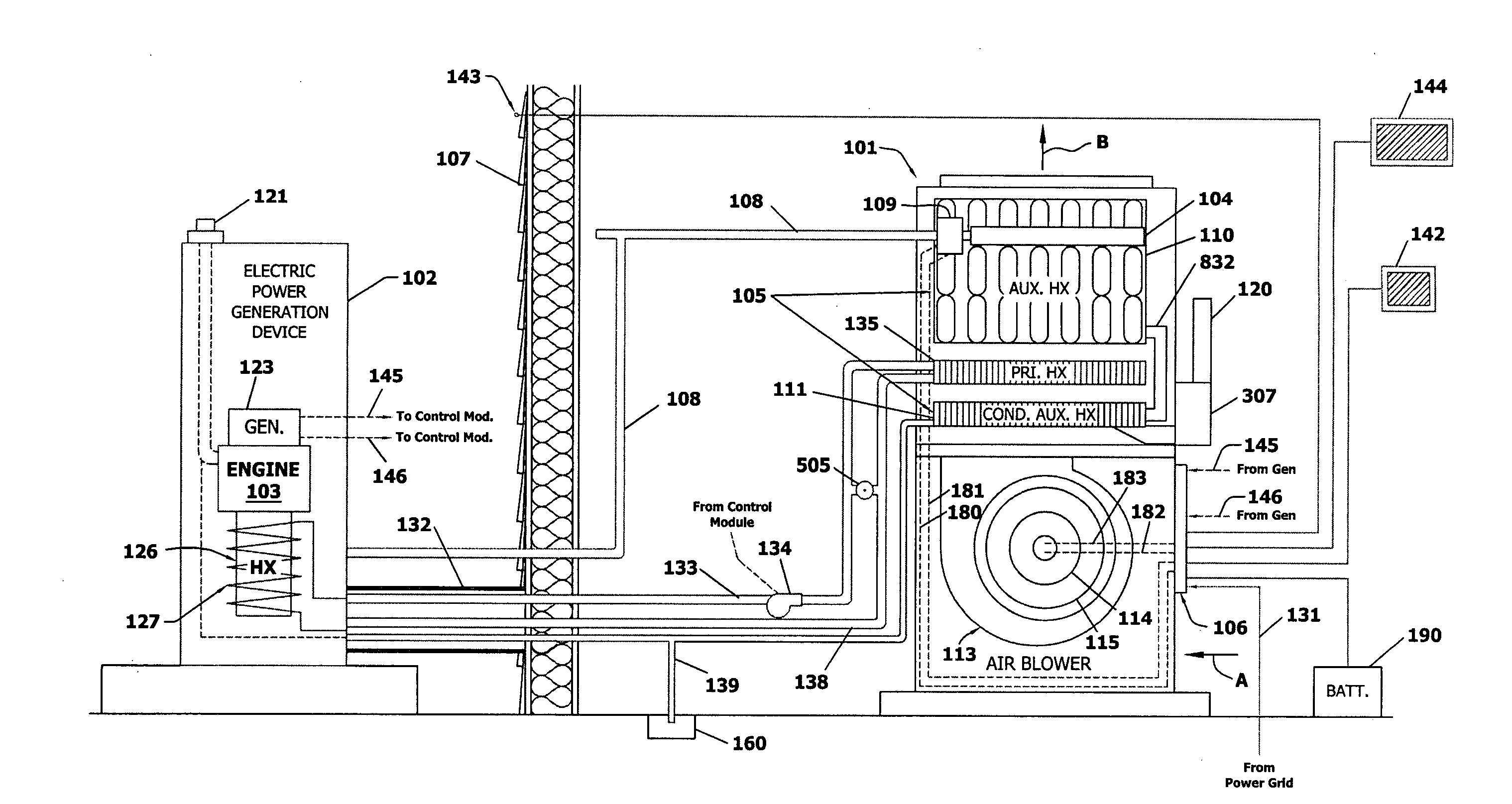
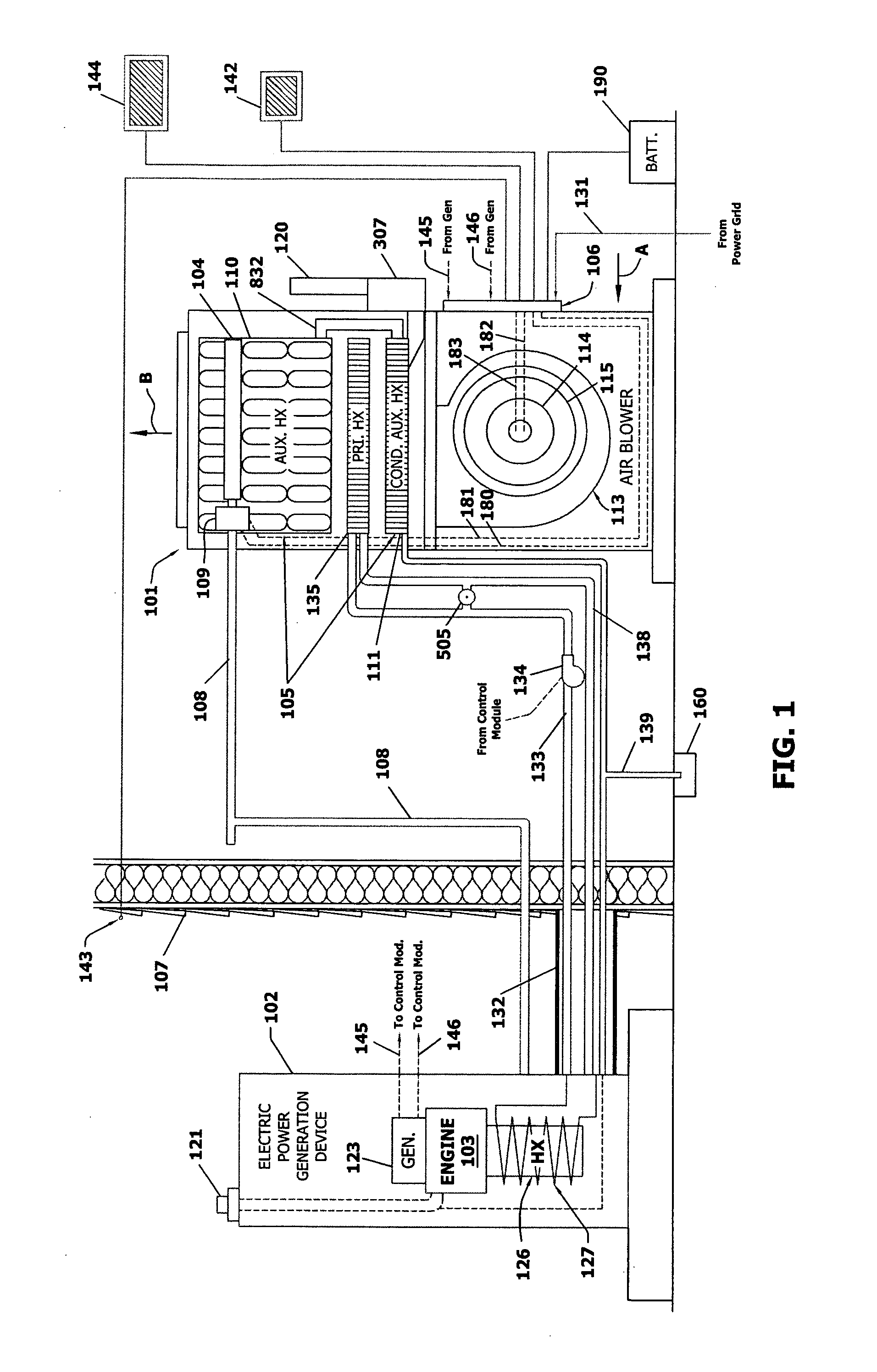
[0022]FIG. 1 illustrates a warm air micro-CHP system installed in a typical residential application according to an embodiment of this invention. The air heating assembly 101 is located within the interior of the residence space. The electric power generator 102 is located outdoors. While not shown, a series of vents and ducts interconnect with the air heating assembly to channel heated (and optionally) cooled air to various points in the structure. For smaller installations, the air heating assembly may vent directly into the space without significant runs of ductwork. Likewise, return air can enter a duct adjacent the system 101 or be channeled from a remote location(s) in the structure via appropriate ductwork (not shown).

[0023] In this embodiment the air heating assembly 101 is interconnected by a coolant loop to a power generator 102 that is located outside the structure, on the opposite side of the building wall 107. As defined herein, the power generator 102 can be any accep...


PUM


Abstract

This invention provides a system and method for cogeneration of building heat and electric power and that efficiently interfaces a warm air heating system with a liquid-cooled electric power generator. The system and method utilizes an electric generator that is rated at near the time-averaged electric power consumption for the building. This generator is operated as the priority source of heat for the building, but normally only when there is a demand for heat in building. In this manner, the generator can run to generate a significant part of the building's electric power but in a manner that is typically supplemented in variable quantities by power from a public power grid. The heat output is directed via a liquid coolant circuit on the generator, as needed, to the warm air heating unit for the building. The warm air heating unit blows return air through a cabinet and out to the supply duct(s). The warm liquid coolant is directed through a primary heat exchanger in the cabinet. The air is passed over this primary heat exchanger to provide heat to the building. When heat from primary heat exchanger is insufficient to heat the building fully, an auxiliary heater, operated typically by burning fuel, supplements the heat through one or more auxiliary heat exchangers arranged in line along the airflow path with the primary heat exchanger. The blower that directs the airflow is controlled variably in speed to create the most efficient use of electric power by the blower and a desirable heated air delivery temperature.

Description

BACKGROUND OF THE INVENTION [0001] 1. Field of the Invention [0002] This invention relates to the cogeneration of space / water heat and electrical power. [0003] 2. Background Information [0004] In most regions of North America, space heating of buildings is a necessity for some portion of the year to maintain thermal comfort. Buildings are space-heated in a variety of ways, with one of the most common being forced warm air heating, using a blower to move the air over a centrally located heat exchanger. The majority of such heat exchangers are warmed directly by using the hot gases produced by a fossil fuel burner. [0005] Buildings also require a source of electric power. Forced warm air space heating systems are in themselves a significant user of electric power. This electric power is normally provided by an electric utility through the local electric grid, with the generation of the electric power occurring at large power stations remotely located from the building. All forms of el...

Claims


Application Information

Patent Timeline
Patent Type & Authority Applications(United States)
IPC IPC(8): F02G1/043F02G5/02F24D3/08F24D5/02F24D18/00
CPCF24D3/08F24D5/02Y02E20/14F24H2240/06F24H2240/00F24D2101/30F24D18/00F24D2105/00F24D2101/70F24D2103/13F24D2105/10F24D2103/17F24D2101/80
Inventor GUYER, ERIC C.
Owner CLIMATE ENERGY
Learn More