Pipe joint seal with closed end face

a pipe joint and seal technology, applied in the direction of fluid pressure seals, cable terminations, mechanical equipment, etc., can solve the problems of ineffective seal between the gasket and the pipe, increased assembly steps, and use of clamping bands, so as to increase the versatility of the gasket, easy slit or cut

Inactive Publication Date: 2005-05-12
SKINNER JAMES W
View PDF16 Cites 6 Cited by
  • Summary
  • Abstract
  • Description
  • Claims
  • Application Information

AI Technical Summary

Benefits of technology

[0013] Advantageously, in applications in which the gasket is not used for a pipe joint, the closed end face of the gasket remains intact, such that the need for a separate end cap for closing the gasket is eliminated. When the gasket is used for a pipe joint, the end face of the gasket may be easily slit or cut away from the remainder of the gasket to create and opening through which a pipe may pass through the gasket. A further advantage is that, because a fluid tight seal is formed by compression of the sealing projection of the gasket between the pipe and the body of the gasket, separate clamping bands are not required to provide a seal between the pipe and the gasket.
[0014] In an alternate embodiment, the gasket includes an auxiliary sealing portion adjacent the closed end face, and can provide a seal with pipes of at least two different outer diameters. The sealing portion may be configured as an inwardly radially projecting portion of the body of the gasket. For providing a seal with a pipe having a relatively larger outer diameter, the gasket is cast in place within the structure, and the closed end face is slit or removed. Thereafter, without folding the sealing projection from the first position to the second position, the pipe is inserted through the gasket, and the sealing portion is compressed between the outer surface of the pipe and the concrete structure to provide a fluid tight seal between the pipe and the structure. If a pipe having a relatively smaller outer diameter is used, the sealing projection is folded inwardly from its first stable position to its second stable position. After the end face is slit or removed, the pipe is inserted through the gasket and the sealing projection is compressed between the pipe and the body of the gasket to form a fluid tight seal with the outer surface of the pipe. Advantageously, the gasket of this embodiment can accommodate two different sizes of pipe, thereby increasing the versatility of the gasket in field installations.

Problems solved by technology

A disadvantage with these types of gaskets is that irregularities in the gasket or in the pipe surface could result in an ineffective seal between the gasket and the pipe.
Although clamping bands are effective, the use of clamping bands requires additional labor and also adds additional assembly steps to the installation of a pipe connection to a structure.
In many applications however, it is not known which openings and gaskets will be used for pipe joints until the structure is actually installed in the field.
Problematically, closing unused openings of the structure with caps requires additional labor during the installation of the structure.
Another problem with known gaskets is that many known gaskets are specifically dimensioned to receive and provide a seal with only pipes of a single, specific size.
Problematically, however, if a structure is cast which includes one or more gaskets embedded in the structure, it is often not known what specific size of pipes will be used to connect to the structure in the field.
If pipes of the particular needed size are not on hand when the structure is installed in the field, obtaining pipes of the needed size could lead to installation delays.

Method used


Image

  • Pipe joint seal with closed end face
  • Pipe joint seal with closed end face
  • Pipe joint seal with closed end face

Examples


Embodiment Construction

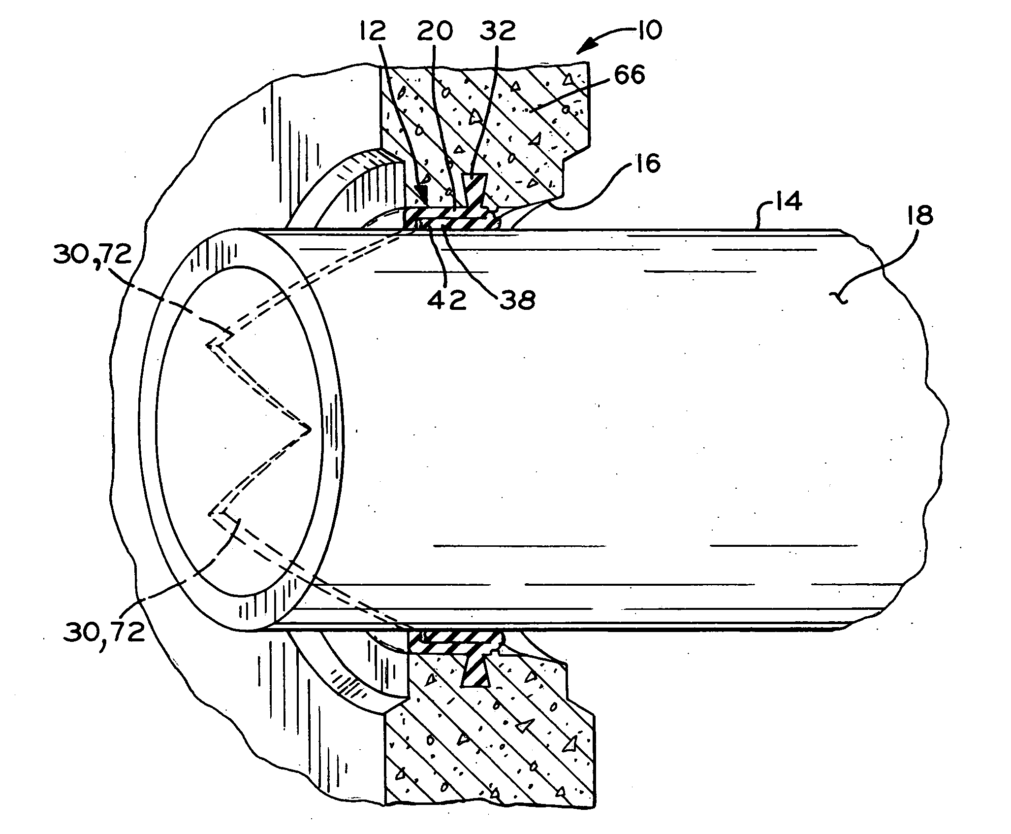
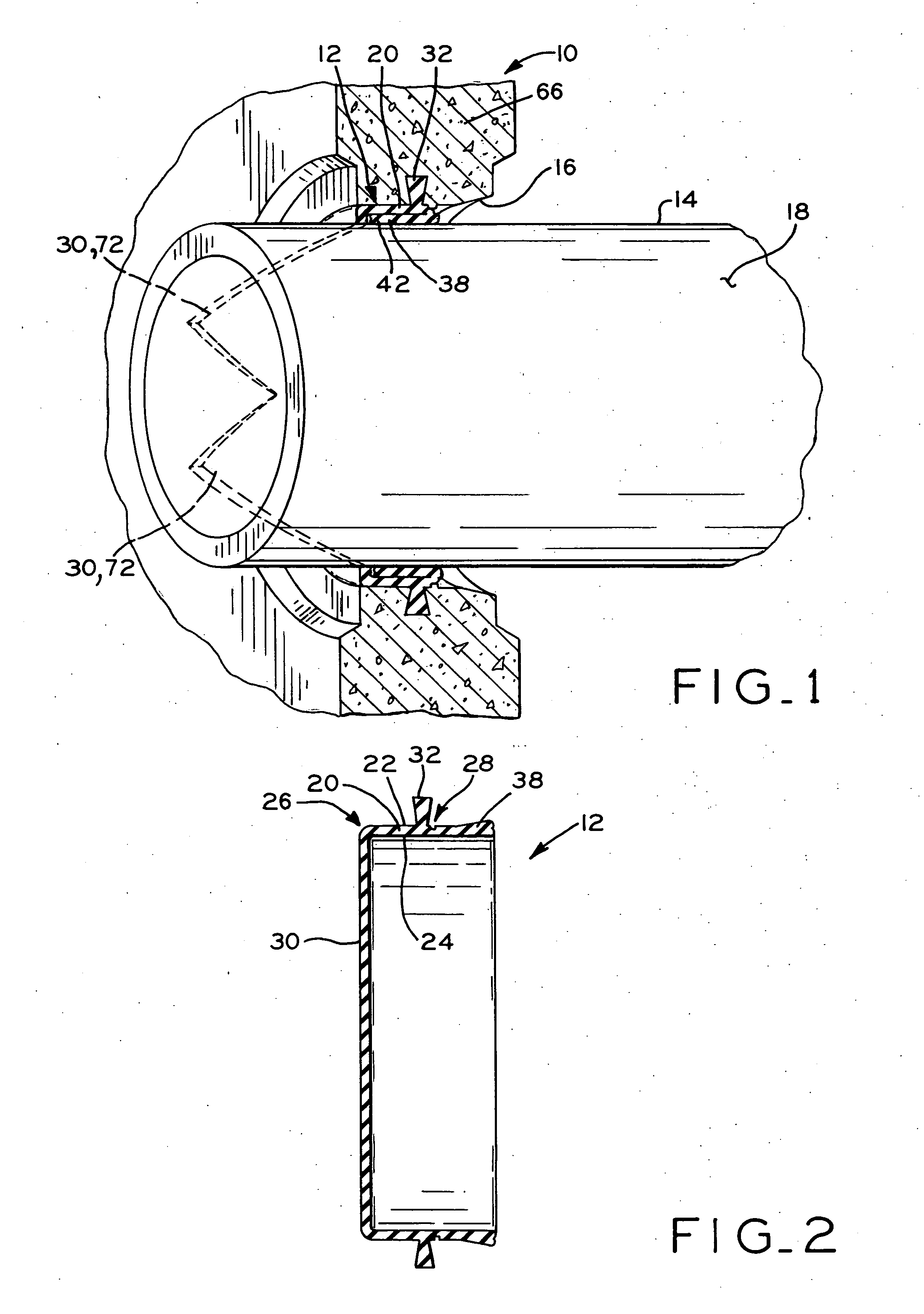
[0034] Referring to FIG. 1, a pipe joint application is shown, including a concrete structure 10, such as a manhole riser, in which at least a portion of a gasket or seal 12 is embedded. Pipe 14 extends through gasket 12, and gasket 12 provides a fluid tight seal between pipe 14 and structure 10. Except as discussed below, the overall structure and function of gasket 12 is similar to the gasket which is described in U.S. Pat. No. 4,809,994, assigned to the assignee of the present invention, the disclosure of which is expressly incorporated herein by reference.

[0035] Although the pipe joint application shown in FIG. 1 and described below is between a pipe and a concrete structure such as a manhole riser, the present gasket may generally be used in any application in which a pipe is mounted to an opening within a structure. For example, the present gasket may also be used in a septic tank having a plurality of inlets to which one or more pipes are respectively connected. Also, althou...


PUM


Abstract

A pipe joint gasket with a closed end face. An annular anchoring projection extends outwardly from the external surface of the gasket and is embedded within a structure with which the gasket is used. The gasket also includes a sealing projection for engaging a pipe to provide a compressive, fluid tight seal between the pipe and the gasket. In applications in which the gasket is used for a pipe joint, the closed end face of the gasket may be slit or removed to allow a pipe to pass through the gasket. Alternatively, in applications in which the gasket is not used for a pipe joint, the end face remains intact, and has a thickness sufficient to withstand internal pressures within the structure and external pressures from without the structure. In an alternate embodiment, the gasket is configured for use with at least two different sizes of pipe.

Description

CROSS REFERENCE TO RELATED APPLICATIONS [0001] This application is a continuation-in-part of U.S. patent application Ser. No. 10 / 461,725, entitled PIPE JOINT GASKET WITH CLOSED END FACE, filed on Jun. 13, 2003, which claims the benefit under Title 35, U.S.C. § 119(e) of U.S. Provisional Patent Application Ser. No. 60 / 467,992, entitled PIPE JOINT SEAL WITH CLOSED END FACE, filed on May 5, 2003.BACKGROUND OF THE INVENTION [0002] 1. Field of the Invention [0003] The present invention relates to gaskets or seals for use in a pipe joint application, in which the gaskets seal a connection between an opening in a structure and a pipe extending through the opening. [0004] 2. Description of the Related Art [0005] In general, pipe joint gaskets or seals are well known in the art for sealing a pipe joint connection between a pipe and a structure in which the pipe is mounted. In one particular application, a pipe joint is formed between a sewer pipe and a concrete manhole riser, for example, in...

Claims


Application Information

Patent Timeline
Patent Type & Authority Applications(United States)
IPC IPC(8): F16L5/10
CPCF16L5/10
Inventor SKINNER, JAMES W.
Owner SKINNER JAMES W
Why Eureka
Try Eureka