
Electric machine

a technology of electric machines and windings, which is applied in the direction of windings, dynamo-electric components, magnetic circuit shapes/forms/construction, etc., can solve the problems of large end windings, time-consuming and labor-intensive, and complicated manufacturing, so as to reduce the manufacturing time of electric machines, improve the electric power and torque parameters, and increase the slot filling degree

Active Publication Date: 2005-05-12
SIEMENS AG
View PDF4 Cites 52 Cited by
  • Summary
  • Abstract
  • Description
  • Claims
  • Application Information

AI Technical Summary

Benefits of technology

[0008] As a result of the configuration of the electric machine according to the present invention, the tooth coils can be directly placed onto the teeth that have rectangular cross section, without requiring winding each wire individually and without requiring an axial split of the lamination piece of the stator. The tooth coils can be prefabricated and secured in the slot by a simple casting process and / or provision of slot wedges. The tooth coil is hereby wound around a coil bobbin or forms a separate structure without coil bobbin.
[0010] By positioning the slots at a small angle, e.g. less than 5 degrees, relative to one another, the casting process results in a wedging effect for the tooth coils in the slots to permanently retain the tooth coils in the slots.
[0011] As a result of the greater slot filling degree, the electric power and torque parameters are improved in comparison to conventional electric machines. Moreover, manufacturing times of the electric machines is decreased.

Problems solved by technology

This is time-consuming and labor intensive.
Common to all these approaches is also the very complicated manufacture.
In addition, these approaches lead to large end windings, and the slot filling factor is relatively low.
As a consequence, part of the flux which could assist the torque formation is shorted and thus becomes ineffective.

Method used


Image

  • Electric machine
  • Electric machine
  • Electric machine

Examples


Embodiment Construction

[0022] Throughout all the Figures, same or corresponding elements are generally indicated by same reference numerals. These depicted embodiments are to be understood as illustrative of the invention and not as limiting in any way. It should also be understood that the drawings are not necessarily to scale and that the embodiments are sometimes illustrated by graphic symbols, phantom lines, diagrammatic representations and fragmentary views. In certain instances, details which are not necessary for an understanding of the present invention or which render other details difficult to perceive may have been omitted.

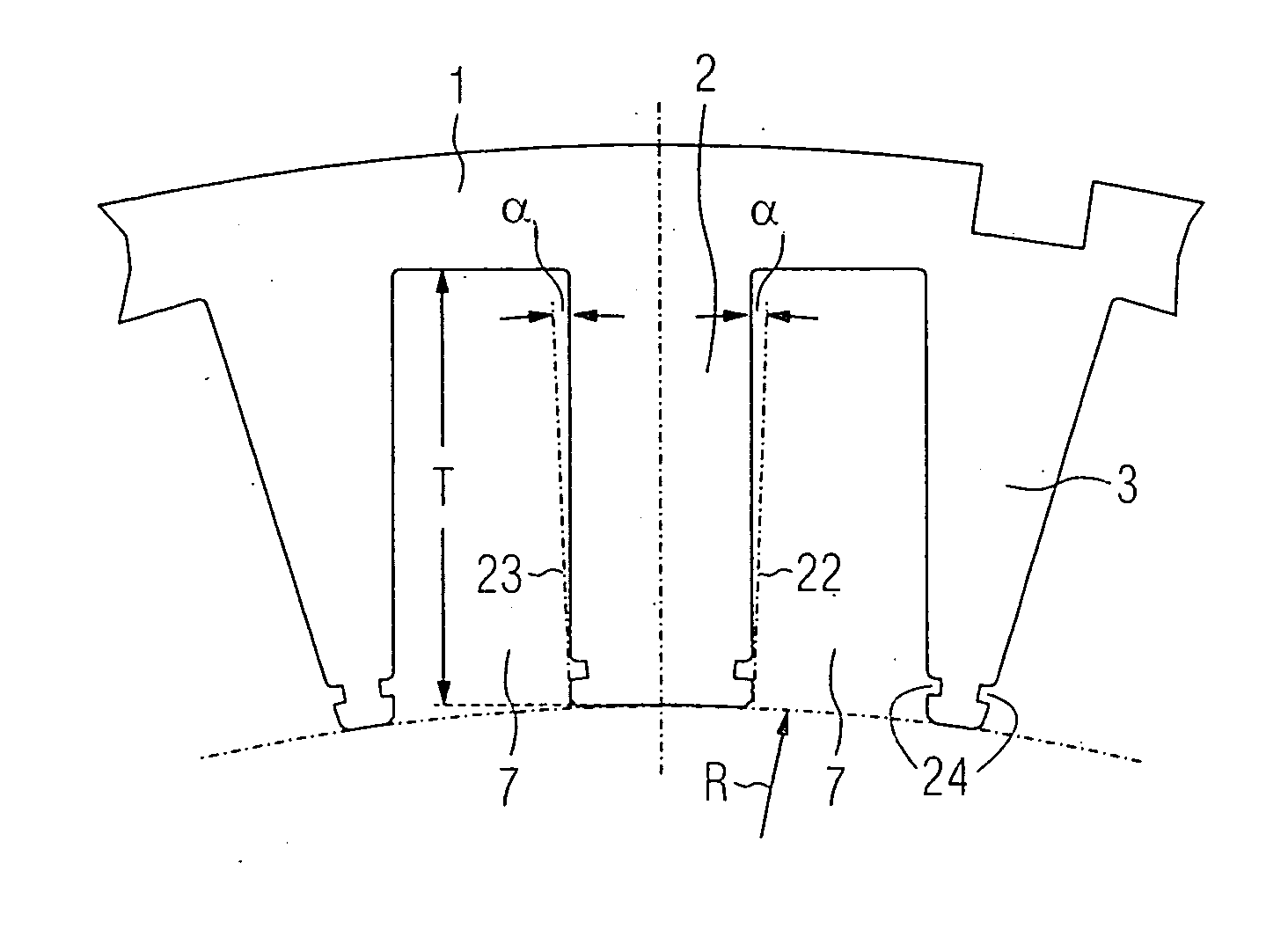
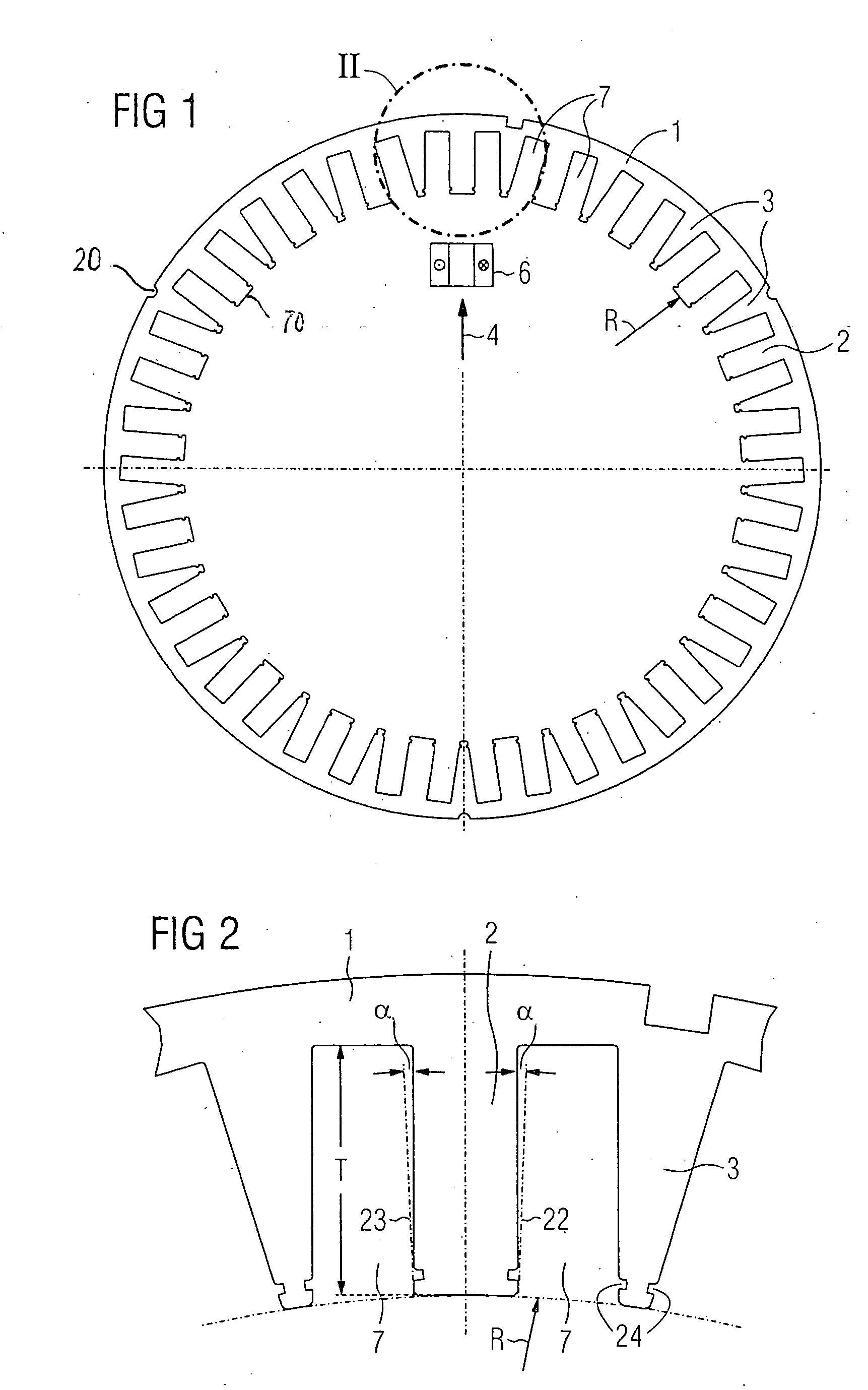
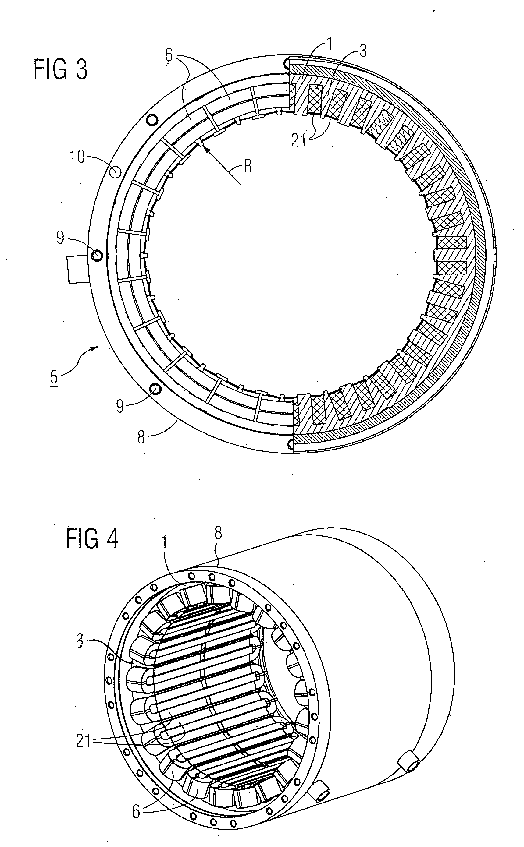
[0023] Turning now to the drawing, and in particular to FIG. 1, there is shown a schematic illustration of a lamination piece 1 according to the present invention which together with like lamination pieces forms a lamination stack of a stator 5 (FIG. 3). Each lamination piece 1 has blanked or stamped therein a plurality of slots 7 to define teeth 2, 3 about the circumference...


PUM


Abstract

An electric machine includes a stator having slots of substantially rectangular cross section. The slots are subdivided into pairs of slots, with each pair of slots configured with parallel flanks, wherein teeth are formed between the slots and have alternating rectangular and triangular cross sections. Positioned on the teeth of rectangular cross section are tooth coils.

Description

CROSS-REFERENCES TO RELATED APPLICATIONS [0001] This application claims the priority of German Patent Application, Serial No. 103 52 814.8, filed Nov. 12, 2003, pursuant to 35 U.S.C. 119(a)-(d). BACKGROUND OF THE INVENTION [0002] The present invention relates, in general, to an electric machine, and more particularly to an electric machine having a stator with slots for positioning tooth coils. [0003] Nothing in the following discussion of the state of the art is to be construed as an admission of prior art. [0004] Coils of electric machines are positioned in slots, i.e. the coils are prefabricated and then positioned in the slots of the electric machine. Machines are also known having pronounced windings to form tooth coils, whereby each winding surrounds a single tooth. These prefabricated tooth coils are positioned from outside into a star-shaped coil bobbin constructed in the form of a stacked metal sheets and pushed into a stator yoke. It is also possible to fabricate the windi...

Claims


Application Information

Patent Timeline
IPC IPC(8): H02K1/14H02K1/16H02K29/03
CPCH02K1/146H02K1/165H02K29/03
Inventor SCHUNK, HOLGERSTORATH, ALBRECHT
Owner SIEMENS AG
Features
  • Generate Ideas
  • Intellectual Property
  • Life Sciences
  • Materials
  • Tech Scout
  • Unparalleled Data Quality
  • Higher Quality Content
  • 60% Fewer Hallucinations
Learn More