Thermal protection for lamp ballasts

a technology for lamp ballasts and ballasts, which is applied in the direction of snap-action arrangements, process and machine control, instruments, etc., can solve the problems of improper heat sinking, inadequate ventilation of lighting fixtures, and overheating of ballasts

Active Publication Date: 2005-05-12
LUTRON TECH CO LLC
View PDF16 Cites 42 Cited by
  • Summary
  • Abstract
  • Description
  • Claims
  • Application Information

AI Technical Summary

Benefits of technology

[0005] A lamp ballast has temperature sensing circuitry and control circuitry responsive to the temperature sensor that limits the output current provided by the ballast when an over-temperature condition has been detected. The control circuitry actively adjusts the output current as long as the over-temperature condition is detected so as to attempt to restore an acceptable operating temperature while continuing to operate the ballast (i.e., without shutting down the ballast). The output current is maintained at a reduced level until the sensed temperature returns to the acceptable temperature.

Problems solved by technology

The maximum operating temperature of the ballast can be exceeded as the result of a number of factors, including improper matching of the ballast to the lamp(s), improper heat sinking, and inadequate ventilation of the lighting fixture.
If an over-temperature condition is not remedied, then the ballast and / or lamp(s) may be damaged or destroyed.
The result is lamp flickering and / or a prolonged loss of lighting.
The flickering and loss of lighting can be annoying.
In addition, the cause may not be apparent and might be mistaken for malfunctions in other electrical systems, such as the lighting control switches, circuit breakers, or even the wiring.

Method used


Image

  • Thermal protection for lamp ballasts
  • Thermal protection for lamp ballasts
  • Thermal protection for lamp ballasts

Examples


Embodiment Construction

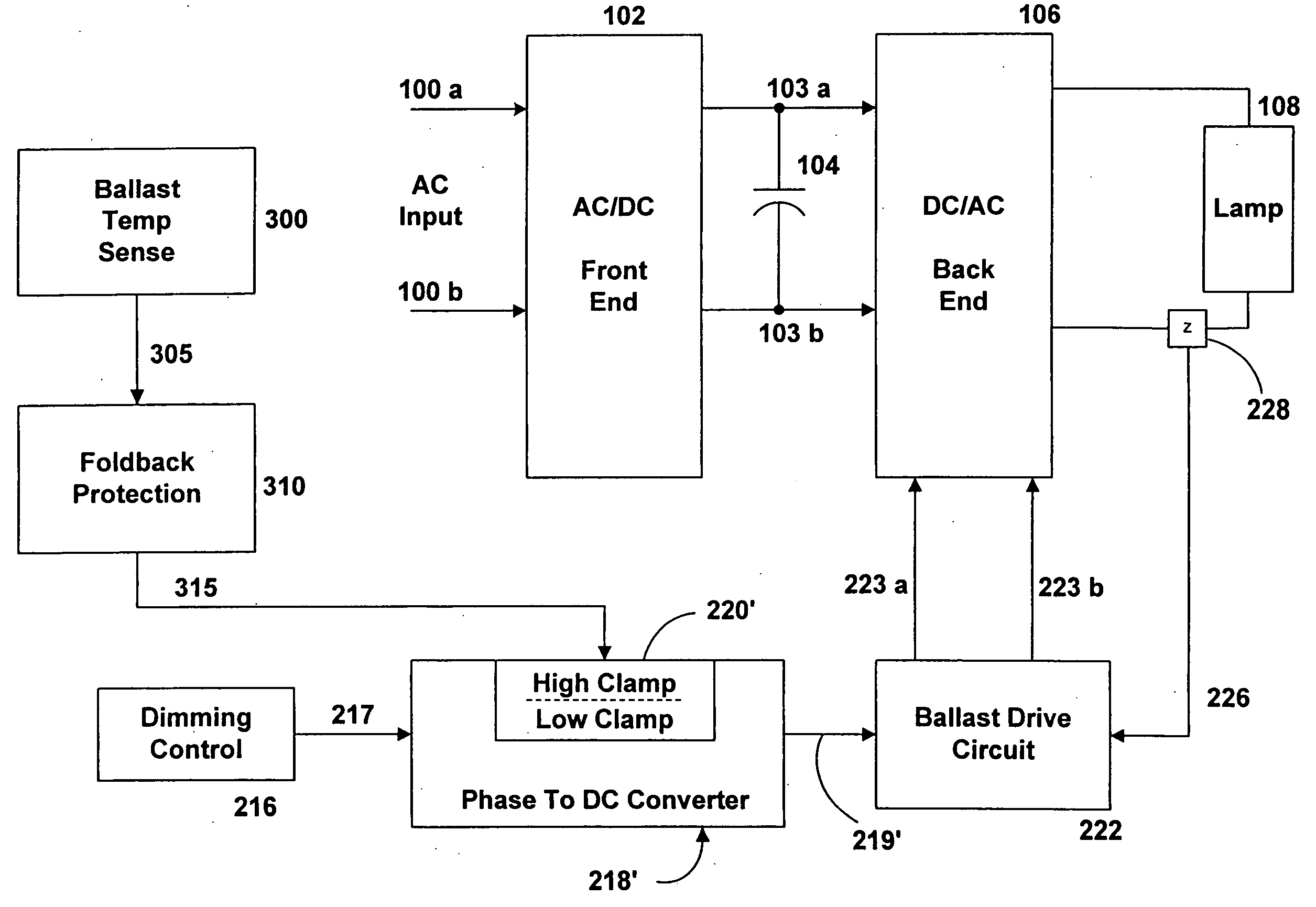
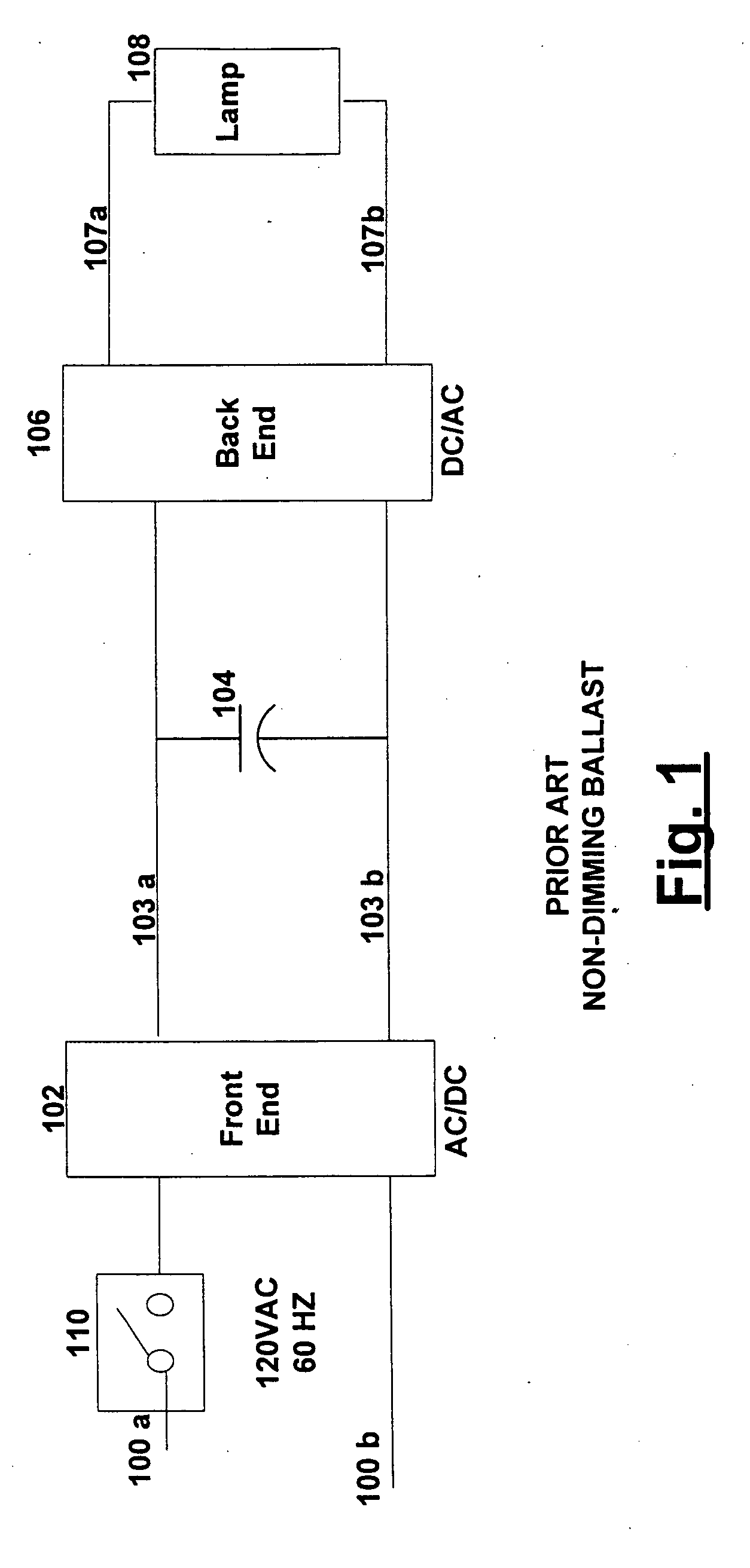
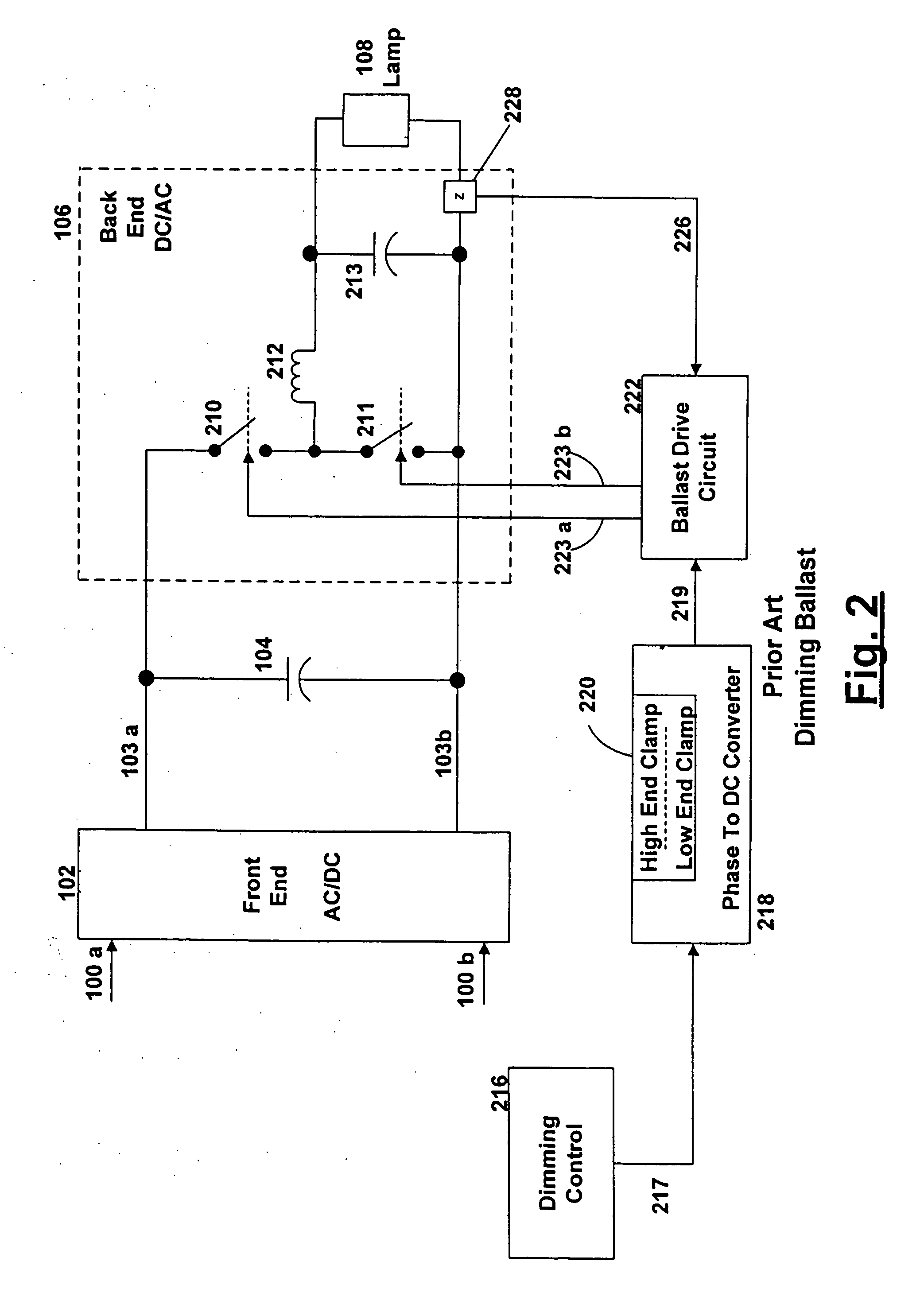
[0026] Turning now to the drawings, wherein like numerals represent like elements there is shown in FIGS. 1 and 2 functional block diagrams of typical prior art non-dimming and dimming ballasts, respectively. Referring to FIG. 1, a typical non-dimming ballast includes a front end AC to DC converter 102 that converts applied line voltage 100a, b, typically 120 volts AC, 60 Hz, to a higher voltage, typically 400 to 500 volts DC. Capacitor 104 stabilizes the high voltage output on 103a, b of AC to DC converter 102. The high voltage across capacitor 104 is presented to a back end DC to AC converter 106, which typically produces a 100 to 400 Volt AC output at 45 KHz to 80 KHz at terminals 107a, b to drive the load 108, typically one or more florescent lamps. Typically, the ballast includes a thermal cut-out switch 110. Upon detecting an over-temperature condition, the thermal cutout switch 110 removes the supply voltage at 100a to shut down the ballast. The supply voltage is restored if ...


PUM


Abstract

The output current of a ballast is dynamically limited when an over-temperature condition is detected in the ballast according to one of (i) a step function or (ii) a combination of step and continuous functions, so as to reduce the temperature of the ballast while continuing to operate it.

Description

FIELD OF THE INVENTION [0001] This invention relates to thermal protection for lamp ballasts. Specifically, this invention relates to a ballast having active thermal management and protection circuitry that allows the ballast to safely operate when a ballast over-temperature condition has been detected, allowing the ballast to safely continue to provide power to the lamp. BACKGROUND OF THE INVENTION [0002] Lamp ballasts are devices that convert standard line voltage and frequency to a voltage and frequency suitable for a specific lamp type. Usually, ballasts are one component of a lighting fixture that receives one or more fluorescent lamps. The lighting fixture may have more than one ballast. [0003] Ballasts are generally designed to operate within a specified operating temperature. The maximum operating temperature of the ballast can be exceeded as the result of a number of factors, including improper matching of the ballast to the lamp(s), improper heat sinking, and inadequate ve...

Claims


Application Information

Patent Timeline
Patent Type & Authority Applications(United States)
IPC IPC(8): H02H5/04H05B41/285H05B41/298H05B41/392
CPCH05B41/2856H05B41/3925H05B41/2986H05B41/285H05B41/298G05F1/00H01H5/04
Inventor COTTONGIM, DAVID E.ARAKKAL, JECKOCHITTA, VENKATESHTAIPALE, MARK S.
Owner LUTRON TECH CO LLC
Why Eureka
Try Eureka